APOGEE ELECTRONICS
7
ROSETTA 200 – User’s Guide
16
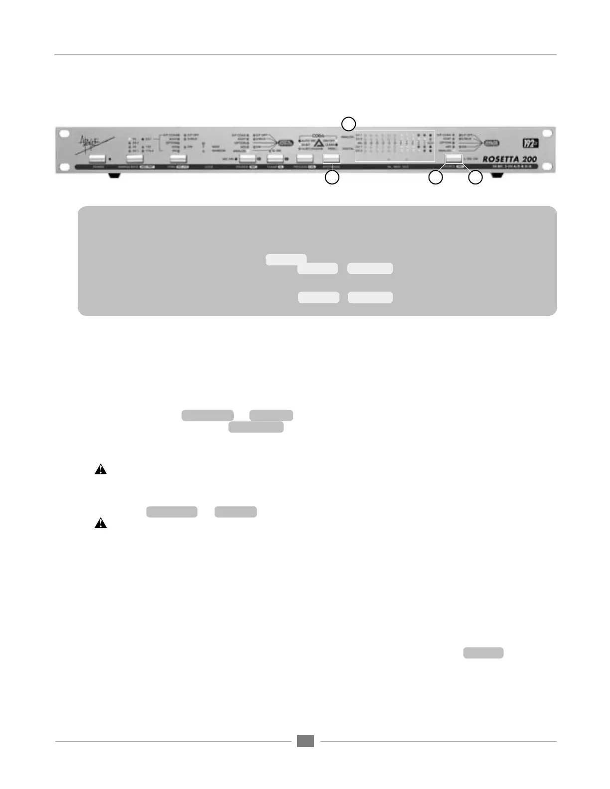
Navigating the Front Panel - continued
15
17
18
Follow these steps to calibrate the Rosetta 200:
1 Before entering CAL mode, set both SOURCE (to Digital Outputs) and SOURCE (to Analog Outputs) to Analog.
2 Connect a 1 kHz tone at the desired analog reference level (usually +4 dBu) to both Analog inputs, and
connect an analog meter (voltmeter or analog VU meter) to the Analog outputs.
3 Engage CAL mode by pressing and holding PROCESS.
4 Select the A/D channel(s) to calibrate, and press the + (CLEAR) or – (SOURCE to Digital Outputs) buttons until the
desired digital reference level is displayed on the corresponding LED bargraph. When only one LED (per channel) is
lit, the A/D is calibrated to within +- .1 db of the specified level.
5 Select the D/A channel(s) to calibrate, and press the + (CLEAR) or – (SOURCE to Digital Inputs)
15) APTOMIZER – A new Apogee technology developed for the Rosetta 200, APTOMIZER sets A/D and D/A
calibration levels by detecting peak level information at the A/D converter and adjusting both analog inputs and
outputs for the optimal setting. Think of APTOMIZER as an alert assistant who constantly re-calibrates the unit
based on the input received (even if “alert assistant” is an oxymoron).
ON-OFF – turns APTOMIZER On or Off. Note that when APTOMIZER is turned Off, calibration levels return to
the last manually adjusted values.
TRIM – Once the Rosetta 200 has determined an optimal calibration level in LEARN mode, it’s possible to trim
this level using the – (SOURCE) and + (CLEAR) buttons. Each button push modifies calibration levels .1 dB.
LEARN – Press and hold the APTOMIZER button to engage LEARN mode. While in LEARN mode,
the A/D calibration level is dynamically adjusted so that the highest peak detected at the analog inputs
results in a digital level of -.5 dBFs. To preserve unity gain through the unit (i.e. what goes in is what
comes out), the D/A calibration level is adjusted simultaneously.
APTOMIZER and Soft Limit – When LEARN mode is engaged, the A/D calibration level drops to its
lowest gain value in order to comfortably accept input peaks up to +24 dBu. To avoid misdetection
of peaks, Soft Limit is disengaged when LEARN mode is engaged. If using Soft Limit, it’s suggested
to check calibration levels once LEARN mode is disengaged, and modify if necessary with the TRIM
buttons (– (SOURCE) and + (CLEAR)).
When engaging LEARN mode, please note that previously detected calibration values set by
APTOMIZER are lost.
16) METERS – These bargraphs display the digital level of both SOURCE selections. When the Rosetta 200 is
configured as an A/D – D/A (i.e SOURCE (to Digital Outputs) is set to Analog and SOURCE (to Analog
Outputs) is set to a digital source), the ANALOG bargraph displays the analog input after A/D conversion
while the DIGITAL bargraph displays the digital input before D/A conversion.
17) SOURCE (to Analog Outputs) – This parameter selects the input source that is routed to the Analog
outputs. When a digital input is selected, the Rosetta 200’s D/A converters are employed to convert the
selected input to digital.
18) SRC (Sample Rate Conversion) – When a digital source has been selected, press and hold SOURCE (to
Analog Outputs) to engage SRC.