APOGEE ELECTRONICS
8
ROSETTA 200 – User’s Guide
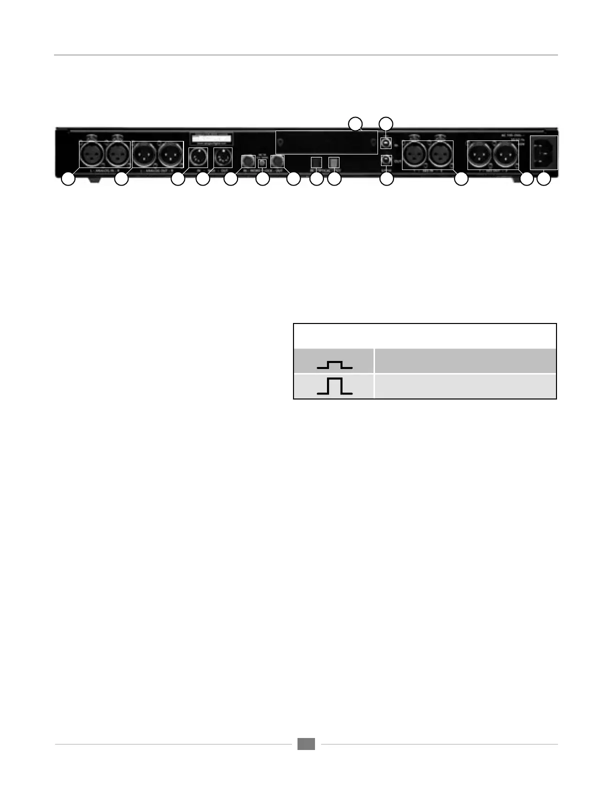
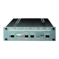
Connections on the Rear Panel
1) L-R ANALOG IN – These female XLR connectors accept balanced analog line inputs, and are adjustable for
a maximum level between +2 and +26 dBu.
2) L-R ANALOG OUT – These male XLR connectors provide balanced analog line outputs, and are adjustable
a maximum level between +2 and +26 dBu.
3) MIDI IN - This 5-pin DIN connector is used to update the Rosetta 200’s firmware, as described on page
9. When an X-FireWire Option card has been installed, MIDI input is routed to a connected computer via
FireWire.
4) MIDI OUT – When an X-FireWire card is installed,
this 5-pin DIN connector outputs MIDI from a
connected computer.
5) WORD CLOCK IN – This BNC connector accepts a
TTL Logic clock signal.
6) WC IN TERMINATION – This pushbutton switch
determines the termination status of the Word Clock In, as depicted in Figure 1.
7) WORD CLOCK OUT – This BNC connector provides a TTL Logic clock signal output.
8) OPTICAL IN – This Toslink connector accepts ADAT, S/MUX and S/PDIF format optical inputs.
9) OPTICAL OUT - This Toslink connector provides ADAT, S/MUX and S/PDIF format optical outputs.
10) OPTION SLOT – This slot accepts X-DigiMix, X-HD and X-FireWire Option cards, which provide additional
digital I/O formats.
11) S/PDIF IN – This coaxial connector accepts S/PDIF format inputs.
12) S/PDIF OUT - This coaxial connector provides S/PDIF format outputs.
13) AES IN 1-2 – These female XLR connectors accepts AES Single and Double Wire format input.; when AES
Single Wire format is employed, use AES IN 1.
14) AES OUT 1-2 - These female XLR connectors provide AES Single and Double Wire format output.; when
AES Single Wire format is employed, both outputs are identical.
15) AC IN
1
3
132
4
5
7
6
8
9
10
11
12
14
15
WORD CLOCK IN, Termination Switch
Terminated switch position
Unterminated switch position
Figure 3