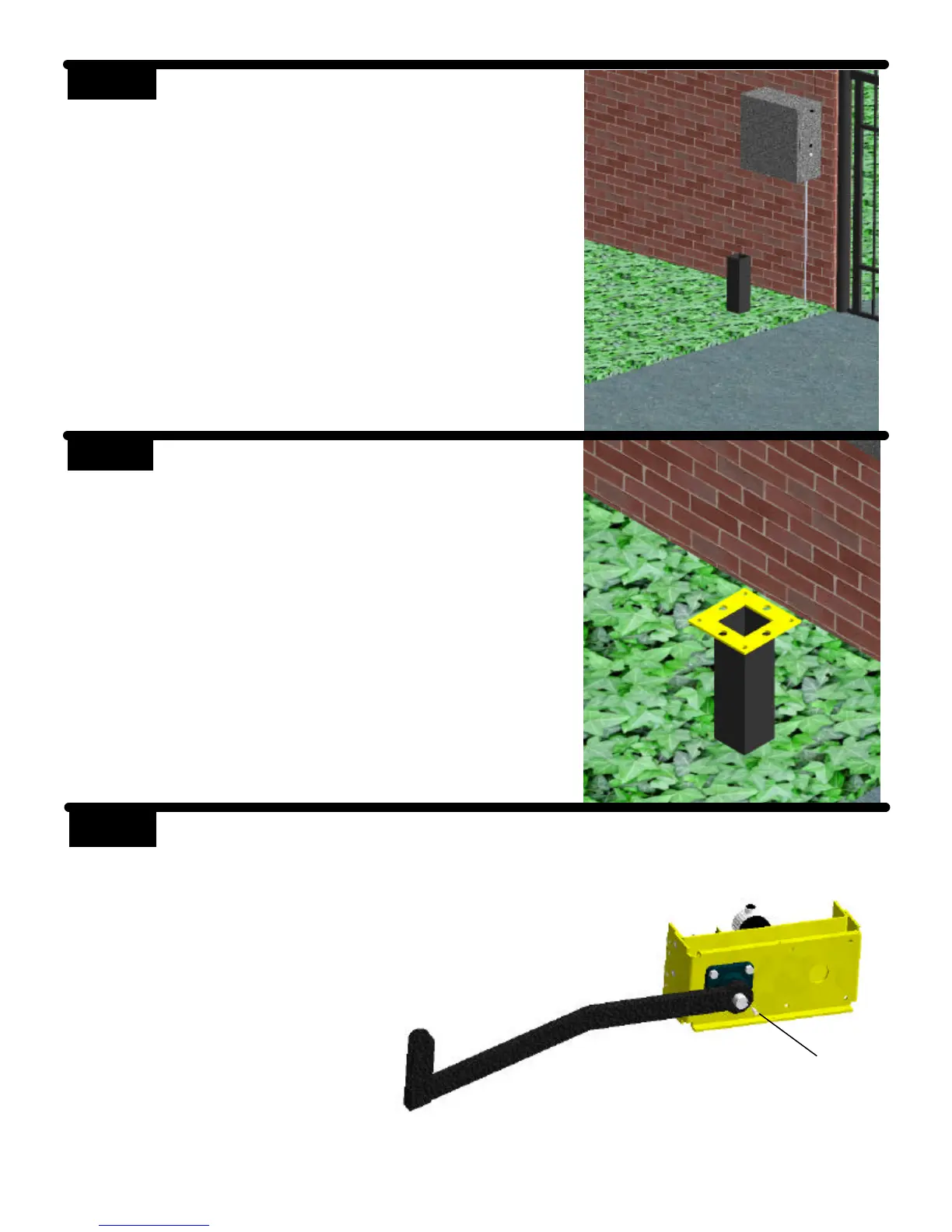
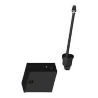
STEP 3
Weld the mounting bracket on top of the
mounting post. The bracket should be
level and square to the post.
Tack welds may be made from the top
side of the bracket and post. Bottom
welds should be made for
permanent rigidity.
Primary Arm
Two Ears
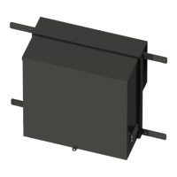
STEP 4 Lay the operator chassis on it’s side.
The two ears on the primary arm
should point toward the direction the
gate will close. Install the primary arm
to the main drive shaft using the 1/4”
key stock and tighten both set
screws. The collar on the primary
arm should be installed on the shaft
as far as possible.
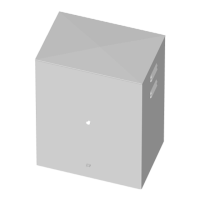
STEP 2
Mount the control box as close to the op-
erator as possible (recommended within 5
feet). Use mounting hardware capable of
supporting the weight of the control box
with the battery installed.
Do not mount the control box where
the person using the push button on
the side of the box can come in con-
tact with the gate.
Set the battery inside of the control box
with the terminals toward the front. (Do
not use batteries with side terminals.)
Key stock