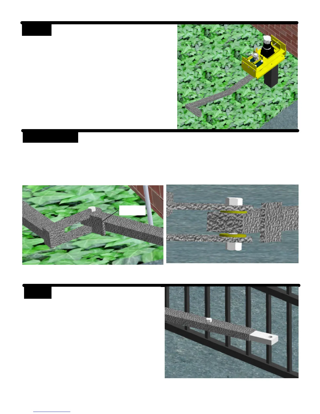
STEP 5
Install the drive unit on the mounting
bracket using (4) 1/2” x 3/4” hex bolts
and lock washers.
STEP 6
Install the secondary arm to the primary arm using a 1/2” x 2-1/4” hex bolt,
brass washers, and lock nut.
The stop tab should be positioned away from the gate.
Stop Tab
STEP 7 Install the adjustable arms to the sec-
ondary arm using the 1/2” x 1-1/2”
hex bolt and nut. Use the middle hole
in the adjustable arm.