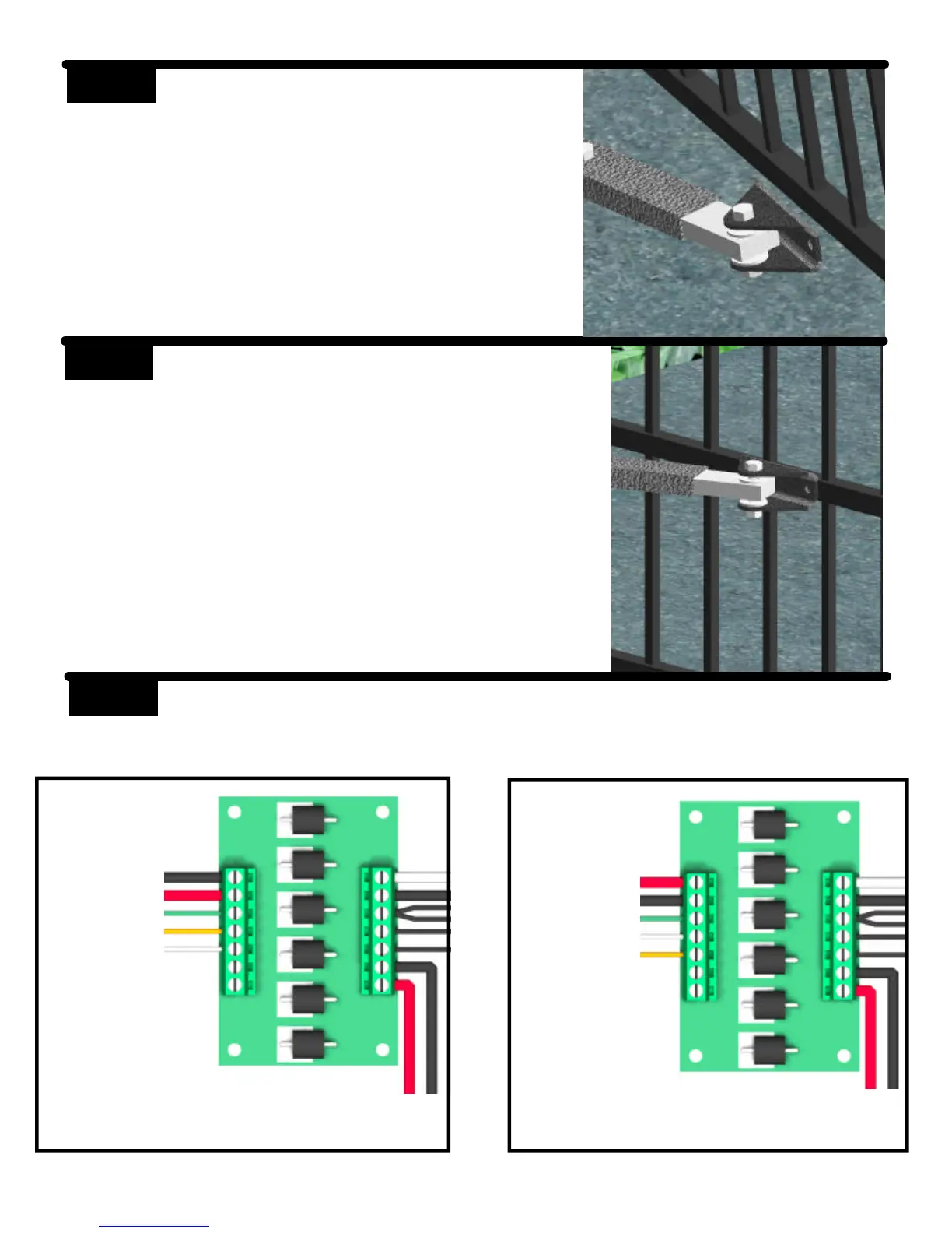
STEP 8 Push the arms assembly up against the
gate in the closed position. Make sure
that the primary arm is locked into the
stop tab on the secondary arm. Tack
weld or c-clamp the gate bracket to the
gate. Permanent welds or bolt attach-
ment should be completed once limits
are set.
STEP 9 Route the cable from the control box to the operator. Connect the cable to the
left side of the terminal block on the operator as shown. The operator in this
manual is set up for left side installation (from inside looking at gate in closed
position).
STEP 7 Install the gate bracket to the adjustable
arm using the 1/2” x 2-1/2” hex bolt,
washers, and lock nut.
Left Side Installation
Right Side Installation
Black
Red
Green
Orange
White
Cable to
Control
Box
Red
Black
Green
White
Orange
Cable to
Control
Box