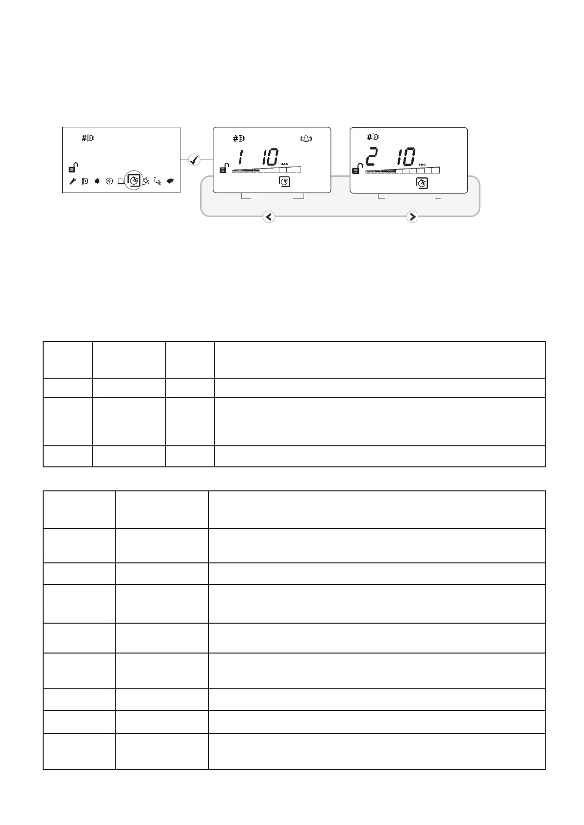
Delay 1 (Fire)
These settings are the delays that the System Controller uses before signalling a FIRE or
FAULT condition respectively to the Fire Control Panel. Default factory setting=10 seconds
D
elay 2 (Fault)
This detector remains in non-latching mode and therefore this setting is not available
(Set for each Detector)
19. Fire/Fault Delay
20. Latching/Non-Latching Mode
14
21. Analogue Value and Output Bits
Output
Bit
Function
Input
Bit
Description
0 Not Used 0 No Action
1 Self Test 1
Initiates the Fire Test within the controller; analogue value 64
will be transmitted if test successful.
2 Alarm LED 2 Illuminate red fire LED on controller and detector.
Analogue
Value
Name Description
0
Microprocessor
fault
Internal communications fault within controller
4 General fault To cover all fault states not covered elsewhere in this table.
5 Signal high fault
Signal >100% or =125% (depending on how quickly signal has
changed)
6
AGC limit
reached
AGC value has reached its lower (-50) or upper (+205) limit.
Also known as ‘Drift Fault’
16
Controller
powering up
System controller is powering up and has yet to establish
communication with detectors
25 Normal
48 Pre-alarm Signal strength has fallen below pre-alarm threshold
64 Alarm
Detector has signalled a fire (i.e. signal below fire threshold
and delay to fire expired)