© Apollo Fire Detectors Limited 2015
8
A127D
OUTPUT 2OUTPUT 1
3V DC
SE
T
RST
INPUT 1 INPUT 2
LED
ENABLE
POWER
INPUT
1
INPUT
2
FAULT
CLOSED
0 1
1
64
F-SAFE
3V DC
SE
T
RST
N/
O
COM
N/
C
N/
O
COM
N/
C
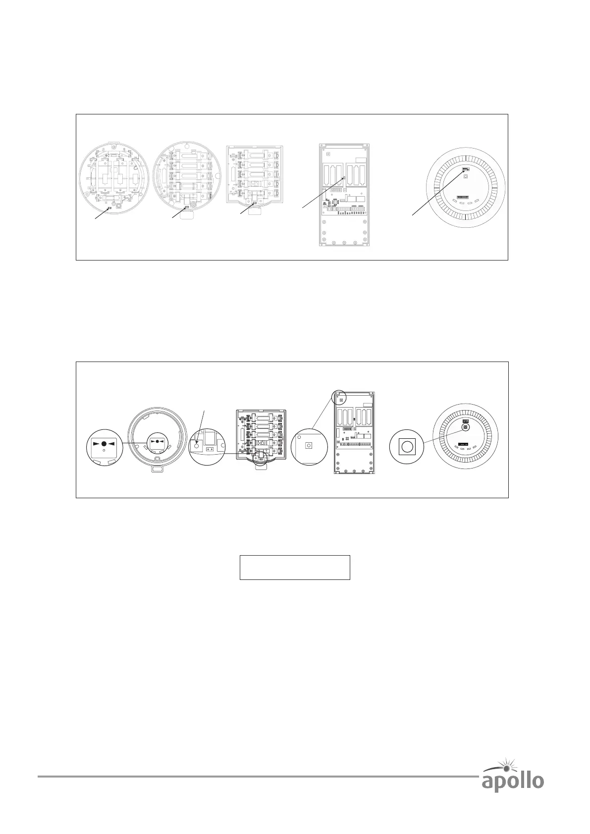
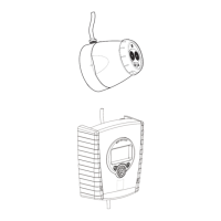
XPander Sounder and
Sounder/Beacon
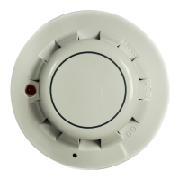
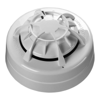
XPander Detector
Base Module
XPander MCP
XPander
I/O Unit
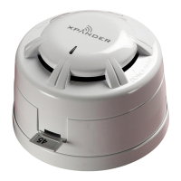
XPander Combined Sounder
and Detector
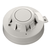
PRESS HERE TO
LOGON
MCP logon button
Detector and Sounder logon button
Input Output Unit logon button
OUTPUT 2OUTPUT 1
3V DC
SET
RST
INPUT 1 INPUT 2
LED
ENABLE
POWER
INPUT 1
INPUT 2
FAULT
CLOSED
01
1
64
F-SAFE
3V DC
SET
RST
N/O
COM
N/C
N/O
COM
N/C
Combined Sounder and Detector logon button
Logon procedure
Ensure batteries are installed correctly and fit the battery jumper (shown below) across both header pins.
Note: The XPander Combined Sounder (Visual Indicator) uses a DIL switch to connect the battery supply.
Push the rotary select switch on the interface and release. Turn until “add new device” is shown on the menu and
push to select. On the device press the log-on button (shown below) for two seconds. A LED on the device will
flash.
A five-figure code will be displayed on the interface similar to below. This is the XPander device’s unique ID.
Turn the rotary select switch to ‘Yes’ and push to select. The menu will return to ‘add new device’.
Check the device’s unique ID against the ID on the label of the product to ensure that it matches.
Repeat steps to add more devices.
Press the ‘Back’ button on completion to return to the previous menu.