9
Machine Usage
STANDARD RECOVERY PROCEDURE
⚠CAUTION
To reduce the risk of injury or product damage, read this entire operating manual, with
particular emphasis on the Safety and Preparation sections (Page 3-8), prior to operating the G1Single.
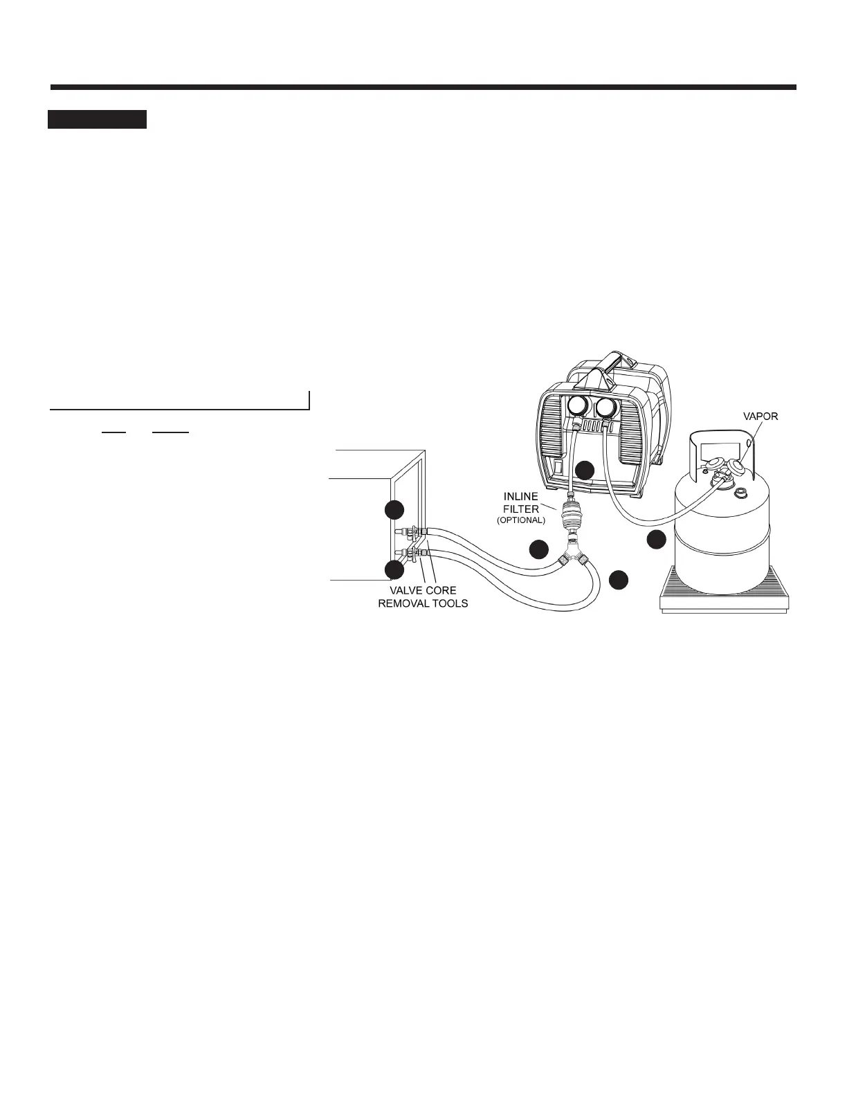
1. Setup the G1Single as shown in Diagram 4 (below). Make sure that all connections are tight.
A. Connect a Valve Core Removal Tool to othe AC/R System Liquid Port.
B. Connect a Valve Core Removal Tool to othe AC/R System Vapor Port.
C. Connect the AC/R System Liquid Port to the Y-Connector.
D. Connect the AC/R System Vapor Port to the Y-Connector.
E. Connect the Y-Connector to the G1Single input port.
F. Connect the G1Single output port to the Vapor Port on the Recovery Cylinder.
Diagram 4
2. Open the Recovery Cylinder Vapor Port.
Make sure to completely open the Recovery Cylinder valve to prevent “output restrictions” (See Tip #1,
Page 14).
3. Turn on the G1Single. The compressor and fan should start.
4. Slowly open the Valve Core Removal Tool ball valve on the liquid port.
Removing liquid first will keep recovery time to a minimum, and improve cooling properties of the
recovery cylinder. NOTE: Overheating or slow recovery speeds may be caused by “input restrictions” (See
Tip #2, Page 14).
5. When all the liquid has been removed, completely open the Valve Core Removal Tool ball valve on the
vapor port. Both sides should now be fully open to maximize vapor flow.
6. Continue to run the G1Single until the EPA-required vacuum is achieved.
7. Close both Valve Core Removal Tool ball valves.
8. Turn o the G1Single.
9. Close the valves on the Recovery Cylinder and disconnect the hoses.
Recover into the Vapor Port of the Recovery
Cylinder for faster recovery.
OPTIONAL: To improve tank cooling, start
with the recovery cylinder upside down,
and flip the tank right-side up near the end
of the vapor recovery.
A
B
C
D
E
F
G1SINGLE OPERATION MANUAL
© 2023 APPION INC. - ALL RIGHTS RESERVED