EasyManua.ls Logo

Application Systems ADX-32 - Rear Panel Connections; Power Input; ADAT Connections 1-4; ADAT Connections 5-8 (ADX-64 only)

Default Icon
14 pages
Print Icon
To Next Page IconTo Next Page
To Previous Page IconTo Previous Page
Loading...
6. Rear panel connections
6.1. Power Input
Power supply of the device.
Use only a DC adaptor with the indicated voltage, power, polarity and matching connector.
On wrong polarity, an internal resetteable fuse is tripped. Disconnect the power supply and wait 10
minutes before connecting again.
The second module in the 64 channel version is internally supplied with power, therefore it is no need
for an additional DC adaptor.
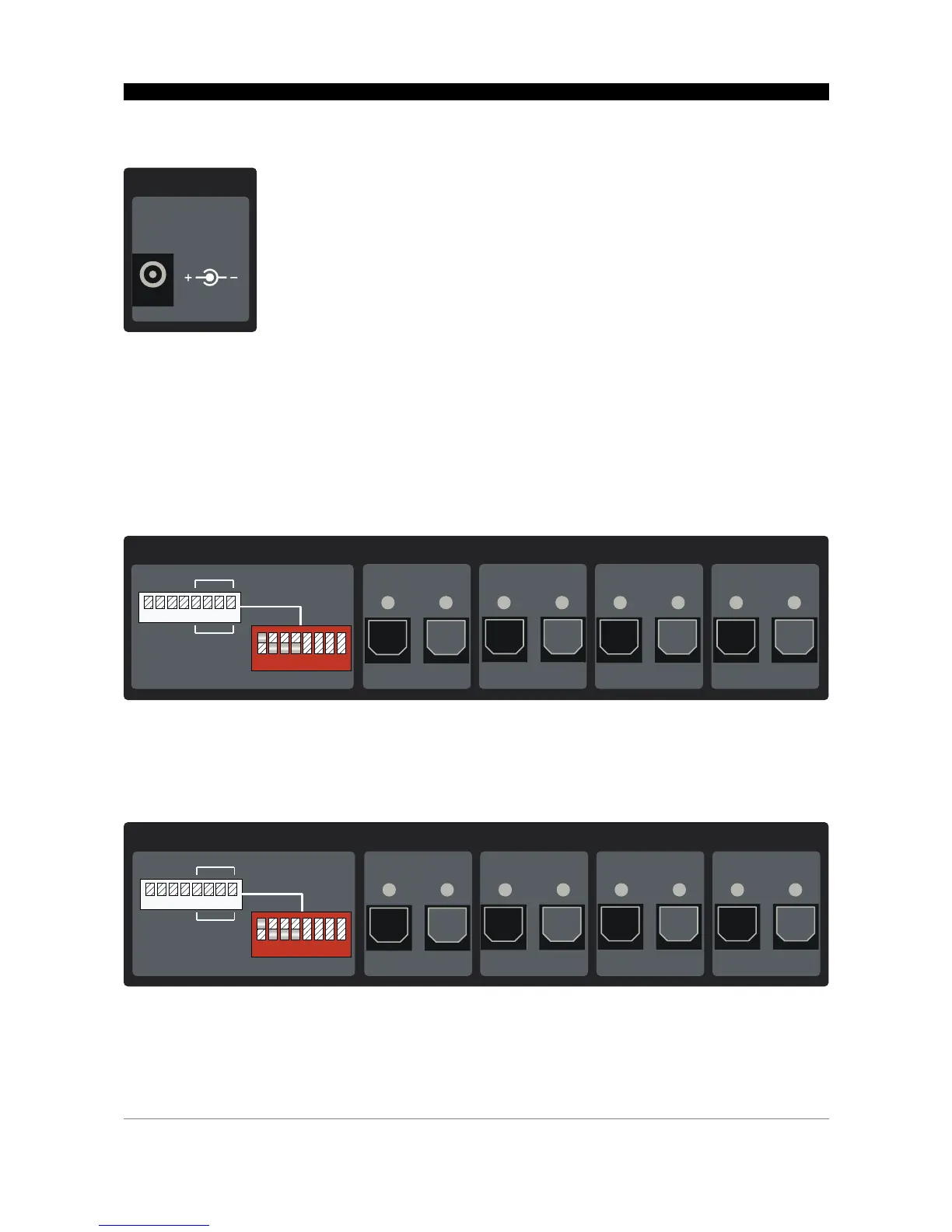
6.2. ADAT Connections 1-4
ADAT Lightpipe inputs and outputs 1-4. The transmission direction (transmit or receive) is set by DIP
switches, see 7.1. Input/output mode (DIP switches 1-4).
6.3. ADAT Connections 5-8 (ADX-64 only)
ADAT Lightpipe inputs and outputs 1-4.
The mode of operation is identical to connections 1-4.
7
8..24V DC
5W
Power input
Ø2.5/5.5mm
1
Input Output
2
1 2 3 4 5 6 7 8
Cat5 cable:
both (A and B)
plugged
3 4
Cat5 cable: only one (A or B) plugged
Input OutputInput OutputInput Output
ADAT Connections 1-4
A
D
A
T
1
:
I
n
p
u
t
A
D
A
T
2
:
I
n
p
u
t
A
D
A
T
3
:
I
n
p
u
t
A
D
A
T
4
:
I
n
p
u
t
O
u
t
p
.
O
u
t
p
.
O
u
t
p
.
O
u
t
p
.
1 2 3 4 5 6 7 8
5
Input Output
6
1 2 3 4 5 6 7 8
A
D
A
T
5
:
I
n
p
u
t
A
D
A
T
6
:
I
n
p
u
t
A
D
A
T
7
:
I
n
p
u
t
A
D
A
T
8
:
I
n
p
u
t
O
u
t
p
.
O
u
t
p
.
O
u
t
p
.
O
u
t
p
.
Cat5 cable:
both (A and B)
plugged
7 8
Cat5 cable: only one (A or B) plugged
Input OutputInput OutputInput Output
ADAT Connections 5-8
1 2 3 4 5 6 7 8