8
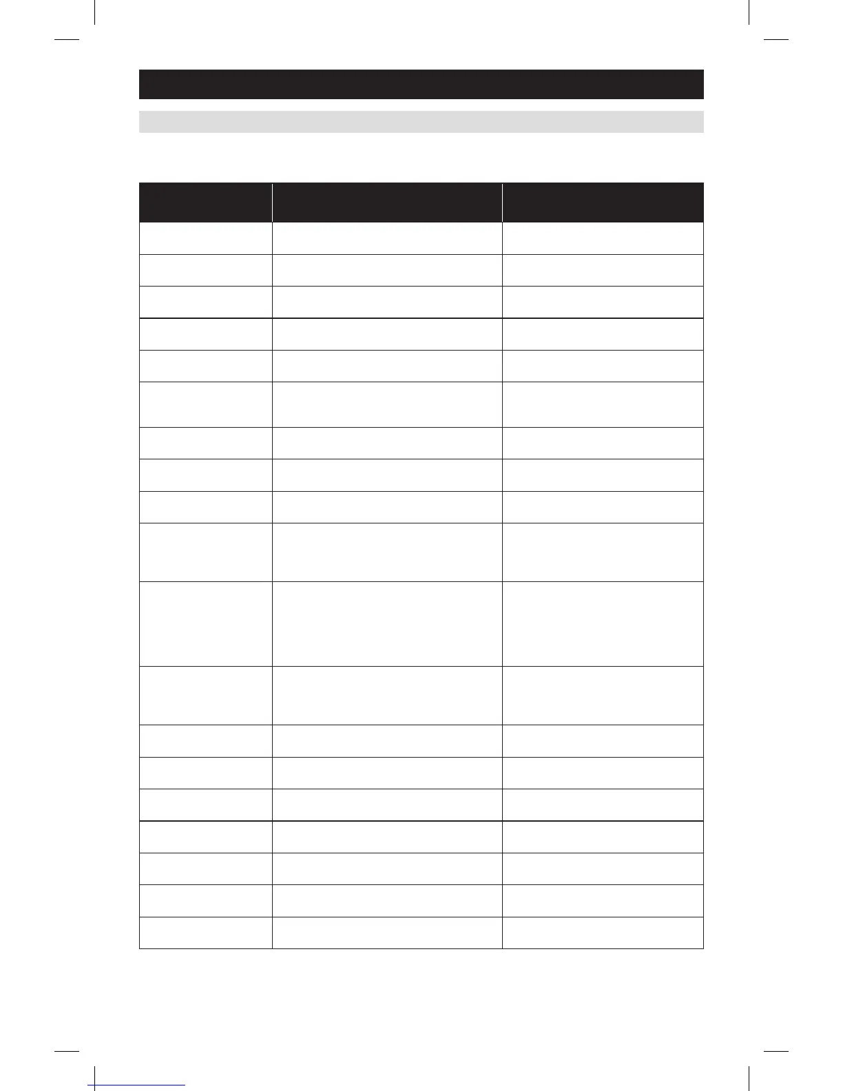
The following table is the list of the settings and their details. Default settings are shown in bold. Some settings are
only available to thermostats set to heat pump or humidistat mode.
INSTALLER SYSTEM SETTINGS TABLE
SETUP & TESTING
System setting Description
Factory default setting (bold)
and setting range
00. NETWORK ADDRESS Network communication address.
1
Address selection of 1 to 64 in steps of 1
01. NUMBER OF NODES Total number of thermostats on the network.
64
Selection of 1 to 64 in steps of 1
02. BAUD RATE Communication baud rate.
9600
19200
03. CONTROLLER TYPE Sets controller to Thermostat or Humidistat.
THERMOSTAT
HUMIDISTAT
04. EQUIPMENT TYPE Equipment type is set by SW1.
HEAT/COOL
HEAT PUMP
05. CONTROL SETUP Used to lockout heating or cooling outputs
(only available in Heat/Cool mode).
HEAT AND COOL
HEAT ONLY
COOL ONLY
06. AUTO CHANGEOVER Enable or disable Auto changeover mode.
DISABLE
ENABLE
07. NUMBER OF STAGES Number of stages of equipment.
SINGLE
MULTI
08. AUX HEAT STAGES Number of stages of auxiliary heat equipment.
ONE
TWO
09. Heat/Cool: FAN
CONTROL IN HEATING
Heat Pump: AUXILIARY
EQUIPMENT TYPE
Heat/Cool: Determines if the thermostat or
equipment controls the fan in heating.
Heat Pump: Auxiliary Equipment type.
1
GAS/OIL HEAT (equipment controls fan)
ELECTRIC HEAT (thermostat controls fan)
10. Thermostat:
COMPRESSOR MIN OFF
TIME
10. Humidistat:
DEHUMIDIFIER MIN
ON/OFF TIME
Thermostat: Minimum off time for compressor
protection.
Humidistat: Minimum on/off time for dehumidifier
protection.
5 MINUTES
1 to 5 MINUTES
11. Thermostat: HEATING
MIN OFF TIME
11. Humidistat: HUMIDIFIER
MIN ON/OFF TIME
Thermostat: Minimum off time for heating.
Humidistat: Minimum on/off time for humidifier.
2 MINUTES
1 to 5 MINUTES
12. EQUIPMENT MIN ON
TIME
Minimum on time for heating and cooling.
2 MINUTES
1 to 5 MINUTES
13. AUTO CHANGEOVER
TIME
Minimum time between heating and cooling calls.
4 MINUTES
1 to 5 MINUTES
14. REMOTE SENSOR Select if remote sensor is attached at T1 and T2.
NO
YES
15. OUTDOOR SENSOR Select if outdoor sensor is attached at S1 and S2.
NO
YES
16. CONTROL SENSOR
BACKUP
Control sensor failure response. STOP CONTROL (enter Error Mode)
USE BUILT-IN
17. FIRST STAGE
DIFFERENTIAL
1st stage differential.
1°F (0.5°C)
1°F to 9°F (0.5°C to 2°C)
18. SECOND STAGE
DIFFERENTIAL
2nd stage differential.
1°F (0.5°C)
1°F to 9°F (0.5°C to 2°C)
1
If utilizing a fossil fuel auxiliary heat system, set to Gas or Oil Furnace. In this setting, the heat pump will lock out before the fossil fuel auxiliary
heat comes on; eliminating the need for a dual fuel kit. If utilizing electric auxiliary heat, set to Electric. In this setting, the heat pump and
electric auxiliary heat are allowed to run simultaneously.
 Loading...