1. DESCRIPTION
Device with Aprimatic microprocessor (15 Watt in stand-by) designed to drive 1 motor
with a maximum power of 680 Watt.
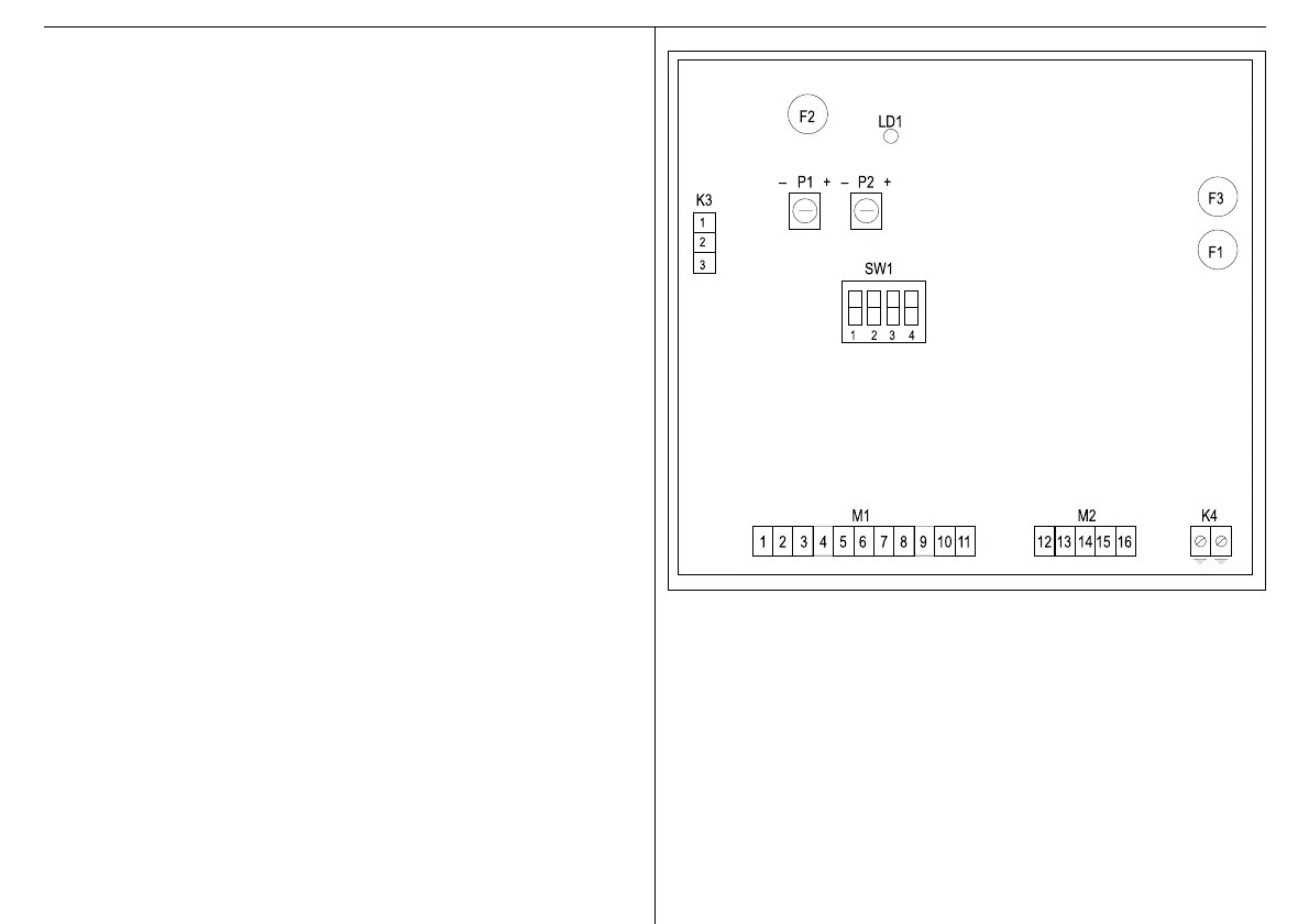
1.1 BLOCK DIAGRAM OF THE DEVICE
P1 Pause time trimmer
P2 Electronic brake trimmer
F1 5A motor fuse
F2 Accessory 500 mA output 24V fuse
F3 200mA transformer fuse
SW1 Dip switch
LD1 Mains presence LED
M1 Signal terminal board
M2 Power terminal board
K3 Radio receiver socket for Aprimatic models only
N.B. Plug in the receiver as shown on the printed circuit.
K4 Earth connection for the device
2. INSTALLATION
CAUTION - The product must only be installed by qualified servicing and/or installation
personnel.
CAUTION - The electrical system must comply with the current regulations in the
country where the product is installed.
CAUTION - Always disconnect the power supply before opening the container. Ensure
that a good earthing system is available and connect it to the appropriate
terminals.
2.1 PREPARATION
Before installing the device, prepare the tools required for securing it to the wall and to
make the electrical connections. The following are also required:
1. expansion wall plugs dia. 6 mm
2. Skintop type PG16 cable clamps
3. a multipole switch with a minimum contact opening of 3 mm
4. an emergency pushbutton
5. approved cables for external use with minimum cross-section of 0.75 and 1.5 mm²
T2.EPS