ECU-C Installation/User Manual
2.Interface Explanation
Interface Layout
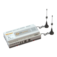
The ECU-C interface includes, (figure 2)from left to right, are Reset、Relay
Feedback Input、Relay Output、Grid CT、Production CT、AC Input.
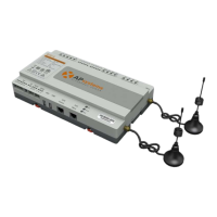
(figure 3)from left to right, are Port、DC、RS232、RS485、USB1、USB2、
RJ45、Internet、RJ45 Signal、AP.
(figure 4)from left to right, are antenna(Zigbee)、antenna(Wifi).
Reset Relay Feedback Input Relay Output Grid CT Production CT AC Input
Figure 2
Port DC RS232 RS485 USB1 USB2 RJ45 Internet RJ45 Signal AP
Figure 3
Antenna(Zigbee) Antenna(Wifi)
Figure 4