U:\Affaires\Aqua-Base\ESW\09- Manuels Utilisateur\DOC UTILISATEUR ESW FRUKES 2023-06-Y3.doc
VERSION 2023-06-Y3
FR/UK/ES
Page 20/52
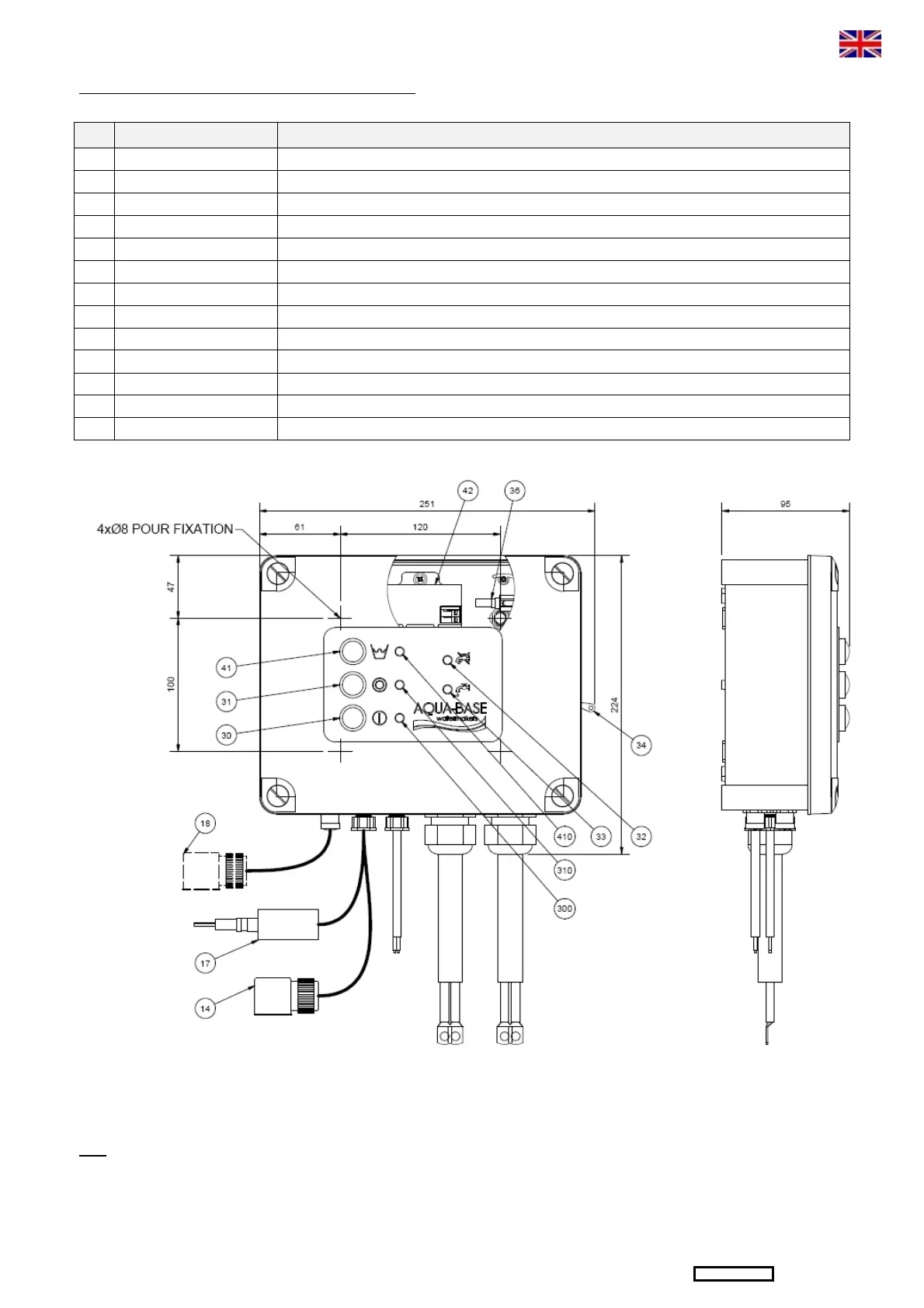
3.2 – ELECTRIC DRAWING AND CONTROL PANEL
Connection of the discharge valve to the salinomet
17 Salinometer cell Measurement of the salinity of the produced water with a cell.
30 Green button Starting up of the unit and lighting up of the green indicator LED.
31 Red button Stopping of the unit.
“Fault in the unit” signal
32 Brackish water signal lamp
Red LED indicating that the production valve is in « discharge » position.
33 Fresh water signal lamp Green LED indicating that the production valve is in « production » position.
Protection of the electric motor if overload.
36 Fuse minifuse Protection salinometer card.
Stopping of the production and start
automatic rinsing timed cycle
410 Rinsing signal lamp Rinsing unit signal LED.
It is recommended to install the control panel near closed to the unit to facilitate the maintenance.
NB: it is possible to install a remote control (see following page)