AquaMaster
®
Owner’s Manual 1/21/2021 10
Installation Steps and Start-Up Procedures, Cont.
Step 5
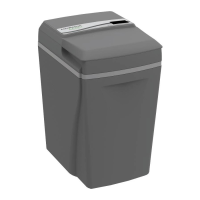
Connect Drain Line
The drain line carries away the backwash water as part
of the regeneration cycle.
A. Connect the drain line to the drain end cap with a
minimum 1/2-inch (12.7-mm) I.D. tubing (supplied).
The size cannot be reduced.
B. Route the drain line to a floor drain, laundry tub, or
other suitable waste receptor. Maintain a minimum
2-inch (50-mm) air gap between the drain line and
the flood level rim of the waste receptor to prevent
back-siphoning. This drain line should make the
shortest run to the suitable drain.
C. The drain line may be elevated up to 8 feet (2.4 m)
from the discharge on the appliance as long as the
water pressure in your system is 40 psi (2.8 bar) or
more.
D. If the drain line is 25 feet (7.6 m) or longer, increase
the drain line to 3/4-inch (19-mm) I.D. The end of
the drain line must be equal to or lower in height
than the control valve.
Caution: The drain line must not be kinked,
crimped, or restricted in any way.
Step 6
Flush Lines
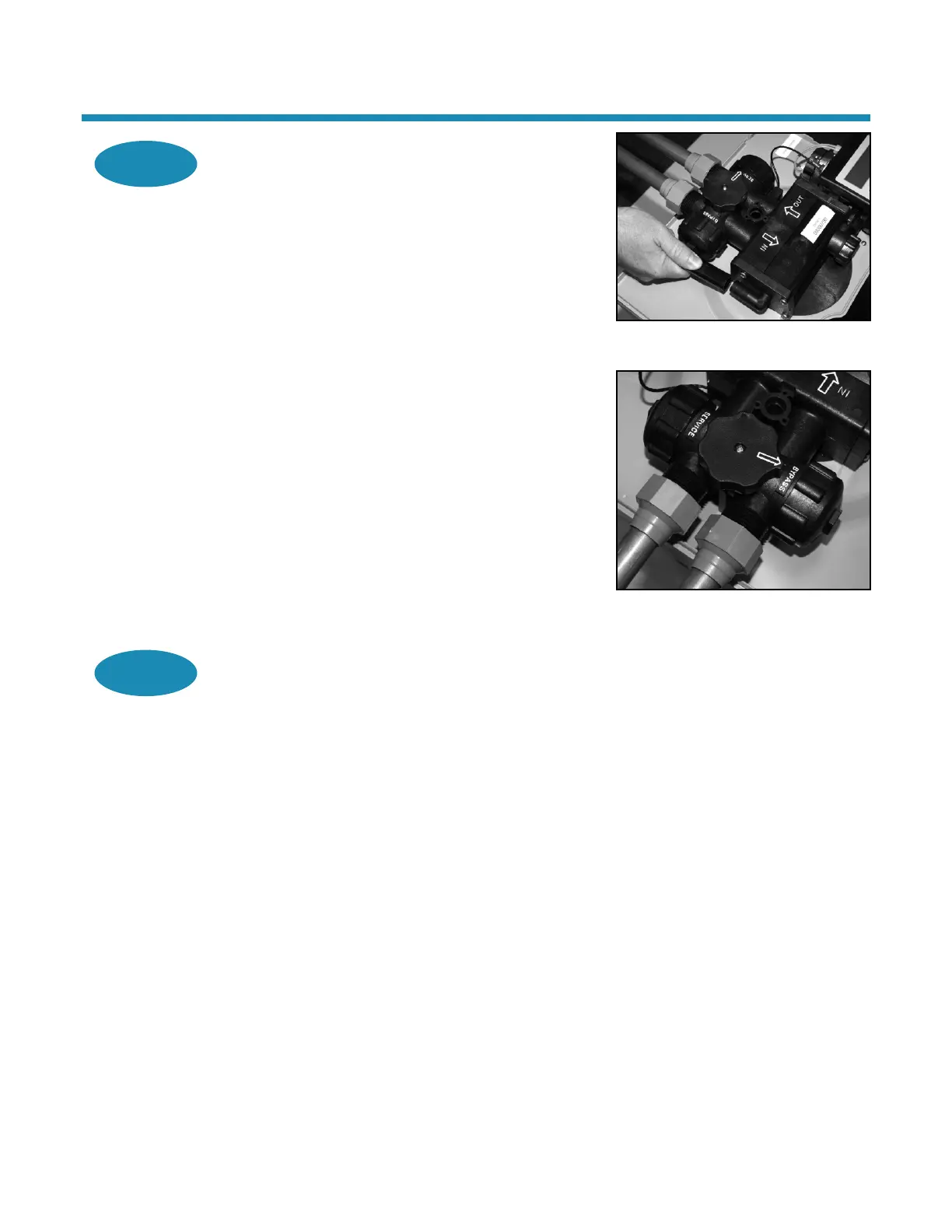
A. Place the appliance in the Bypass position.
B. Turn on the main water supply.
C. Open the nearest cold water faucet to flush the
plumbing of any excess soldering flux, air, or any
other foreign material.
Figure 2: Connect Drain Line
Figure 3: Bypass Position