4
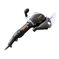
4. ASSEMBLY
ITEM DESCRIPTION
1 Rear handle
2 Trigger switch
3 Lock-off lever
4 Lock on button
5 Top Handle
5
TITLE:
ASSEMBLY NO.
DRAWING NO.
EST. MASS:
DRAWN BY:
DATE:
CHECKED:
APPROVED:
SHEET:
ASSEMBLY NOTES:
CONFIDENTIAL
COPYRIGHT AND DESIGN
RIGHTS REMAIN THE SOLE
PROPERTY OF ARBORTECH
INDUSTRIES PTY LTD.
PROPRIETRY INFORMATION
DISCLOSURE OR
REPRODUCTION PROHIBITED
WITHOUT WRITTEN
APPROVAL FROM ARBORTECH
INDUSTRIES PTY LTD.
67 WESTCHESTER RD MALAGA
WESTERN AUSTRALIA 6062
PH. +618 9249 1944
12345678910111213
A
B
C
D
E
F
G
H
I
A
B
C
D
E
F
G
H
I
12345678910111213
A3
1 OF 3110079146.430 kg SCALE: 0.100BT
AS175-A001-00AS175-A001-01
ALL MATERIALS TO BE ROHS
COMPLIANT
09-Oct-18
AS175
AS180-A005-AA
UNSPECIFIED TOLERANCES
TO FOLLOW ISO-2768-F
DIMENSIONS IN MILLIMETRES
ARBORTECH INDUSTRIES PTY LTD
REV
DETAILS
APRVD DATE
A ISSUED FOR REVIEW
QTY.MATERIALPART NAMEPART NO.INDEX
1AISI_1020DRIVEN PULLEYAS175-P003-AC1
1AISI_1020TENSION IDLERAS175-P004-AA2
1AISI_4140DRIVE PULLEYAS175-P002-AB3
1AL6061RIGHT HAND HOUSINGAS175-P012-024
4FE40TPTR_7211_35
1NYLONbody_back_as180_a_c.prtBODY_BACK_AS180_A_C6
1NYLONbody_mid_as180_a_c.prtBODY_MID_AS180_A_C7
1PA6-GF30BELT COVERAS175-P021-018
1PA6-GF30VACUUM ADAPTERAS175-P010-AA9
1STAINLESS_STEEL_MARTENSITICSPRING GUARDAS175-P008-0110
2AS175-P009-0111
4M4X12_SCREW12
4TPTR_6010_113
5TPTR_6012_014
4TPTR_6014_015
2TPTR_6016_016
1TPTR_6019_017
2TPTR_6022_018
1TPTR_6024_019
1TPTR_6025_020
1TPTR_6026_021
2TPTR_6028_022
4TPTR_6029_023
1TPTR_6031_024
1TPTR_7087_225
2TPTR_7093_1
26
1TPTR_7205_027
1TPTR_8096_128
1TPTR_10011_229
2TPTR_AS_6008_030
1as170-a005-01.asmAS175-A005-0131
1as175-a001-ac.asmAS175-A003-AC32
1as175-p006-aa.prtAS175-P006-AA33
1as175_a004_01_top-handle.asmAS175_A004_01_TOP-HANDLE34
1AS180-P002-01AS180-P002-0135
1circlip_i19.prtCIRCLIP_I1936
1dwe4277-air-baffle.prtDWE4277-AIR-BAFFLE37
1O-RING-BS020O-RING-BS02038
1optibelt_epj.prtOPTIBELT_EPJ39
1optibelt_ph.prtOPTIBELT_PH40
1optibelt_pj260.prtOPTIBELT_PJ_EXT_IDLER41
1optibelt_pj280.prtAS175-P022-042
1tptr-9094-0-rh.asmTPTR_9094_0_RH43
1tptr_8119_7.asmTPTR_8119_744
1tptr_9094_0_lh.asmTPTR_9094_0_LH45
SCALE 0.500
1
TITLE:
ASSEMBLY NO.
DRAWING NO.
EST. MASS:
DRAWN BY:
DATE:
CHECKED:
APPROVED:
SHEET:
ASSEMBLY NOTES:
CONFIDENTIAL
COPYRIGHT AND DESIGN
RIGHTS REMAIN THE SOLE
PROPERTY OF ARBORTECH
INDUSTRIES PTY LTD.
PROPRIETRY INFORMATION
DISCLOSURE OR
REPRODUCTION PROHIBITED
WITHOUT WRITTEN
APPROVAL FROM ARBORTECH
INDUSTRIES PTY LTD.
67 WESTCHESTER RD MALAGA
WESTERN AUSTRALIA 6062
PH. +618 9249 1944
12345678910111213
A
B
C
D
E
F
G
H
I
A
B
C
D
E
F
G
H
I
12345678910111213
A3
2 OF 3110079146.430 kg SCALE: 0.250BT
AS175-A001-00AS175-A001-01
ALL MATERIALS TO BE ROHS
COMPLIANT
09-Oct-18
AS175
AS180-A005-AA
UNSPECIFIED TOLERANCES
TO FOLLOW ISO-2768-F
DIMENSIONS IN MILLIMETRES
ARBORTECH INDUSTRIES PTY LTD
REV
DETAILS
APRVD DATE
A ISSUED FOR REVIEW
4
3 2
TITLE:
ASSEMBLY NO.
DRAWING NO.
EST. MASS:
DRAWN BY:
DATE:
CHECKED:
APPROVED:
SHEET:
ASSEMBLY NOTES:
CONFIDENTIAL
COPYRIGHT AND DESIGN
RIGHTS REMAIN THE SOLE
PROPERTY OF ARBORTECH
INDUSTRIES PTY LTD.
PROPRIETRY INFORMATION
DISCLOSURE OR
REPRODUCTION PROHIBITED
WITHOUT WRITTEN
APPROVAL FROM ARBORTECH
INDUSTRIES PTY LTD.
67 WESTCHESTER RD MALAGA
WESTERN AUSTRALIA 6062
PH. +618 9249 1944
12345678910111213
A
B
C
D
E
F
G
H
I
A
B
C
D
E
F
G
H
I
12345678910111213
A3
2 OF 3110079146.430 kg SCALE: 0.250BT
AS175-A001-00AS175-A001-01
ALL MATERIALS TO BE ROHS
COMPLIANT
09-Oct-18
AS175
AS180-A005-AA
UNSPECIFIED TOLERANCES
TO FOLLOW ISO-2768-F
DIMENSIONS IN MILLIMETRES
ARBORTECH INDUSTRIES PTY LTD
REV
DETAILS
APRVD DATE
A ISSUED FOR REVIEW
5. OPERATION
1) Setup
WARNING: It is recommended that the tool
always be supplied via a residual current device with a
rated residual current of 30mA or less.
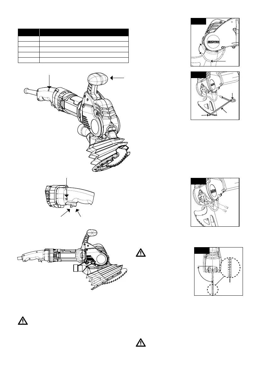
The AS175 is supplied ready for operation. However in
some cases the blades may need to be changed to suit
the application.
Before changing blades,
the guard around the
blade mounts must be
levered gently out of its
groove at the front of the
tool and swung away to
give access to the cap
screws. (See Fig.1)
Guard
Fig.1
Use the “Ian key”
supplied to loosen and
remove the cap screws
securing the blades, then
remove the blades as
shown in Fig.2.
Ian Key
Fig.2
Hold near
end
Torque
indicator
coil
Select the correct blades for the cutting task and mount
each with their cap screws . Verify that the surfaces of
the blade mounts, conrod thread and screws are clean
and free of grit or lubricant before fitting. Ensure the
guard can be closed before fixing the blades to the
conrod (See Fig.2).
NOTE: Always use matched pairs of blades. Never
mix used blades with new blades. Use only the bolts
supplied with the tool.
Use the “Ian key” (see
Fig.2), to tighten the
blade mounting screws
until the torque indicator
coil deflects sufficiently
so that the sides meet.
The “Ian Key” will tighten
the bolts to the required
18Nm (13.2 ft lb).
Fig.3
NOTE: Blades are a wearing part. In normal
operation, blade life may vary with the hardness of
materials cut.
CAUTION:
Do not operate the tool if the
blades are loose. Operation
with loose blades will severely
damage the blade mount &
bolts requiring repair.
Check that the teeth of the
blades are lightly contacting,
or within approximately
1.5mm (1/16”) of contacting
each other (Fig.4).
Fig.4
90
o
1.5mm Max
(1/16”)
If the gap between the blades is too large, remove and
gently bend inward to adjust the gap.
Ensure that both blades are aligned vertically to the tool
(See Fig.4).
CAUTION: If the blades rub against each other
anywhere other than within 25mm/1” of the cutting
edge, or contact force is high, it is possible to overload
the tool and cause premature belt wear.
 Loading...