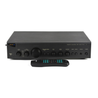
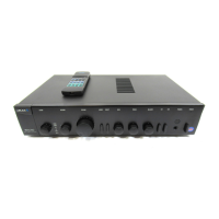
C30 preamp
lifier circuit description
.
In
troduction
The
C30
pr
e-amplifier uses pre-amp input
switching/control and display boards that are
very similar in design to the boards used in
both the Diva A85/A90 and Fmj A32
integrated
amplifiers and as such you may
already be familiar with the layout and
topologies of these boards. The C30 boasts a
very much over-engineered power supply and
output stage that is designed to bring the very
best out of the existing Pre-amp input
switching board.
The main PCB L958AY also contains output
buffers for the unbalanced outputs to drive
long cables and balanced line drivers. A
headphone amplifier is included to drive low
impedance headphones down to 32 Ohm.
For description of the pre-amplifier switching
and control board see the section...
Power supply.
The mains input comes in via SKT1. Two Y
caps return common mode noise to the
chassis ground and an
X cap
reduces any
single ended noise. The
1M5
resistor
following this is in place to discharge the
capacitors when the unit is turned off.
The mains selector switch, which follows the
resistor, changes the configuration of the
transformer windings from series for 230V to
parallel for 115V. Tx1 is a standby
transformer it powers the microcontroller at all
times so that the unit can be put into and out
of standby. To reduce voltage losses after
this transformer, low forward drop diodes are
used. A low drop out regulator follows to
create the
4.5v(D)
supply; this supply powers
the micro and digital circuits.
The primary of the Toroid supply transformer
Tx2 is connected to CON3 and the power to
this is switched on and off by the relay RLY1.
The transformer has a number of secondary
outputs and we use separate taps and bridge
rectifiers networks followed by bulk
capacitors to smooth the ripple. The voltages
generated are +24V and -24V for the main
analogue supplies, +
46V
for the
HT
supply to
the
VFD
, and
+18V
, which is used to power
the trigger output. The smoothed
+/- 24V
then goes through regulators
REG 2
and
REG 5
to create
+/- 18V
this is passed the
pre-amplifier PCB via
CON4.
Another set of
regulators
REG 3
and
REG 6
follow taking
the
18V
and creating a
+/-15V
supply that is
available for add on modules such as the 7.1
channel input board. A 5v supply is derived
via regulator
REG 4
from the
18V
to run the
headphone amplifier.
Mains detect.
A mains present detector runs from the
standby transformer, this detects the loss of
mains using a peak hold circuit based around
D7/TR1/DZ1 and TR2. If the power is lost this
piece of circuitry sends a flag to the
microcontroller so it can mute the outputs
and shut down the unit. See Fig 1 for notes
on
protection modes
.
12v trigger and RC5 receiver.
The trigger output on
SKT2
is driven through
TR4
to provide a current limited supply at
around 13V.
IC1 A
and
B
are used to demodulate
incoming
RC5
from socket SKT2. IC1A is a
band-pass filter centred on
36KHz
. This is
followed by a peak detector circuit that
demodulates the incoming signal.
Fig 1. Protection and mute mode and
measurements.
Prot line Measured at. Working
reading
AC present Resistor R12 +4.5v
Mute* Con 8 Pin 5 +4.5v
Standby* Resistor R5 at
point P18
.7v
Trigger ResistorR10 at
point P54
+1.8v
 Loading...