Display board
The
display board is very similar in design to
the board that has been used for many years
in the A85 family of products inc FMJ A32
and as such those of you familiar with these
products will know there way around this
board, a full description follows.
The power supply rails for the display board
are derived from the main board we should
expect to see the below supplies in place (Fig
2.)
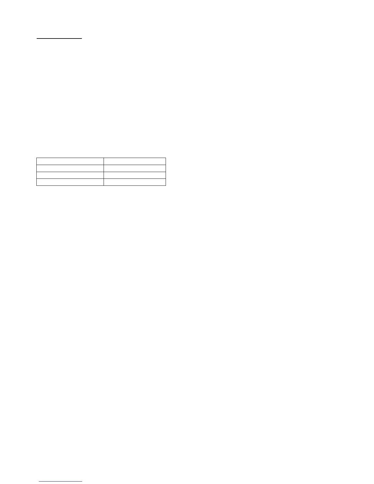
Fig 2 Display board power supply pins
Power supply Pin number of SK1
+ 5v D.C (micro) Pin 14
+ 5v D.C Pin 1
+ 46v D.C for VFD HT Pin 3
P
lease note: the H8 micro is very critical of
the +5v supply and as such the unit may
crash or fail to power up during use if the +5v
supply drops below 4.5v.
H8 Microprocessor
The
H8
micro at location
Z1
is pre-
programmed by Arcam using a flash-
programming module and cannot be
reprogrammed in the field unless you have
access to the appropriate hardware and
software.
The
H8
forms the heart of the C30 and takes
on all major control functions including.
1
. Control of the input switching.
2. Controls the action of the volume cont.
3. Monitors protection status and mute lines
A85/A90/A32 only.
4. Sends display information to the VFD.
5. Receives and decodes RC5 data.
6. Receives data from rear panel remote
input.
7. Stores setting information via 24C02 E-
prom.
At
initial power up the H8 micro is reset by
Z2
a
DS1233
econo reset package.
The input switching information is driven out
to the Pre-amp card via the 9 select lines that
appear on Pins 14 – 22 of SK3.
The Volume control and tone control circuits
are driven from the
SDATA
–
SLOAD
and
SCLK
data lines from SK3.
The Mute status line has control over the
pre-amp output relay at location
RLY100
; the
mute is triggered during power up/down and
between input selections and under Mute
commands.
Within the C30 the
DC prot
,
Therm
,
VI prot
and
SP1/SP2
control lines are all connected
to Digital ground on the main board of the
pre-amp as these are not required within this
product.
The H8 drives the
VFD
via 4 Data lines that
can be seen on R64 – R67 as
DISPDAT
,
DISPCLK
,
DISPBLK
,
DISPLAT
these drive
directly into the VFD.
Remote Data
can be received by the C30 via
the 3.5 mm Phono jack on the rear of the
Pre-amp and the previously described
remote demodulator on the main board this
demodulated RC5 arrives on the display
board via
Pin 3
of
SK1
and goes into a
common IR input pin of the H8 micro (
pin 87
)
this pin is also used to pick the RC5 code up
from the Display onboard remote receiver.
At power up
the H8 reads all previously
stored and last settings used by the amplifier
from the e-eprom at location IC5 these will
include the last input used and tape settings
also tone control and input level settings, any
changes to the set-up of the amplifier are
sent to the e-eprom for future recall, at power
down the H8 downloads it’s settings to the e-
eprom.
All indication LED’s
are driven directly from
the H8 micro, these LED’s are tagged onto
the +5v rail via 10k current limiting resistors
Q1 and Q2 form a toggle between Green and
Red for the standby/power LED.
The volume control
is driven from a Rotary
encoder at location
SW18
the toggle lines
from the encoder arrive at the H8 as control
lines Phase A and Phase B on
Pins 93
and
94.
 Loading...