11
I/O Connections
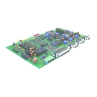
The RC210 supports connecting external devices (other than radios of course) by the use of a DB25 connector. The pinout is
as follows:
Pin Name
Description Pin Name Description
1 AD1 Analog Channel 1 14 UF6 Logic Output 6
2 AD2 Analog Channel 2 15 UF7 Logic Output 7
3 AD3 Analog Channel 3 16 IN1 Logic/Alarm Input 1
4 AD4 Analog Channel 4 17 IN2 Logic/Alarm Input 2
5 AD5 Analog Channel 5 18 IN3 Logic/Alarm Input 3
6 AD6 Analog Channel 6 19 IN4 Logic/Alarm Input 4
7 AD7 Analog Channel 7 20 IN5 Logic/Alarm Input 5
8 AD8 Analog Channel 8 21 VCC +5 for ADC reference - 25 ma MAX.)
9 UF1 Logic Output 1 22 FAN Fan Output
10 UF2 Logic Output 2 23 Future Use
11 UF3 Logic Output 3 24 Future Use
12 UF4 Logic Output 4 25 GND Analog Ground
13 UF5 Logic Output 5

 Loading...