18
Audio Delay Expansion Headers
Audio from the receiver buffers is routed through pin header connectors on the PC board to allow connection of the Arcom
repeater audio delay (RAD) board. This board provides an audio delay of approx. 60 ms, which removes DTMF bursts and
squelch tail crashes from the transmitted audio. If the board is not connected, there must be jumpers in place between pins (pins
2 & 3) of JP10, JP11 and JP12 to complete the audio path from receivers to the crosspoint switch.
Checking COS And PTT Operation
Once connections are made, the next step is to verify that COS and PTT are operating properly. There are a series of LED's on
the RC210 that are used to indicate the status of various functions. Their function is marked on the PC board. They may be
turned off to save power when you don't need them by removing the jumper from JP13. By observing the LED's, you can easily
verify COS, PTT, CTCSS and DTMF operation.
Setting Audio Levels
Refer to the PCB layout at the end of this manual while making adjustments. If you do not have a signal generator or
oscilloscope, you might want to explore the use of a Sound Card based Audio Spectrum Analyzer program available from
InterFlex Systems Design Corporation. It can be helpful to measure audio levels, look for distortion, twist in the DTMF tones, etc.
Using a signal generator, generate a signal on the receiver's frequency with 1000 Hz modulation @ 3 Khz deviation. Keep in
mind that for best quality audio and to avoid clipping, we want the minimum amount of amplification necessary. An oscilloscope
should be used to measure the voltage. Following the Table 5, adjust the appropriate trimpot for a level of .75 volt peak-to-peak
at the corresponding test point.
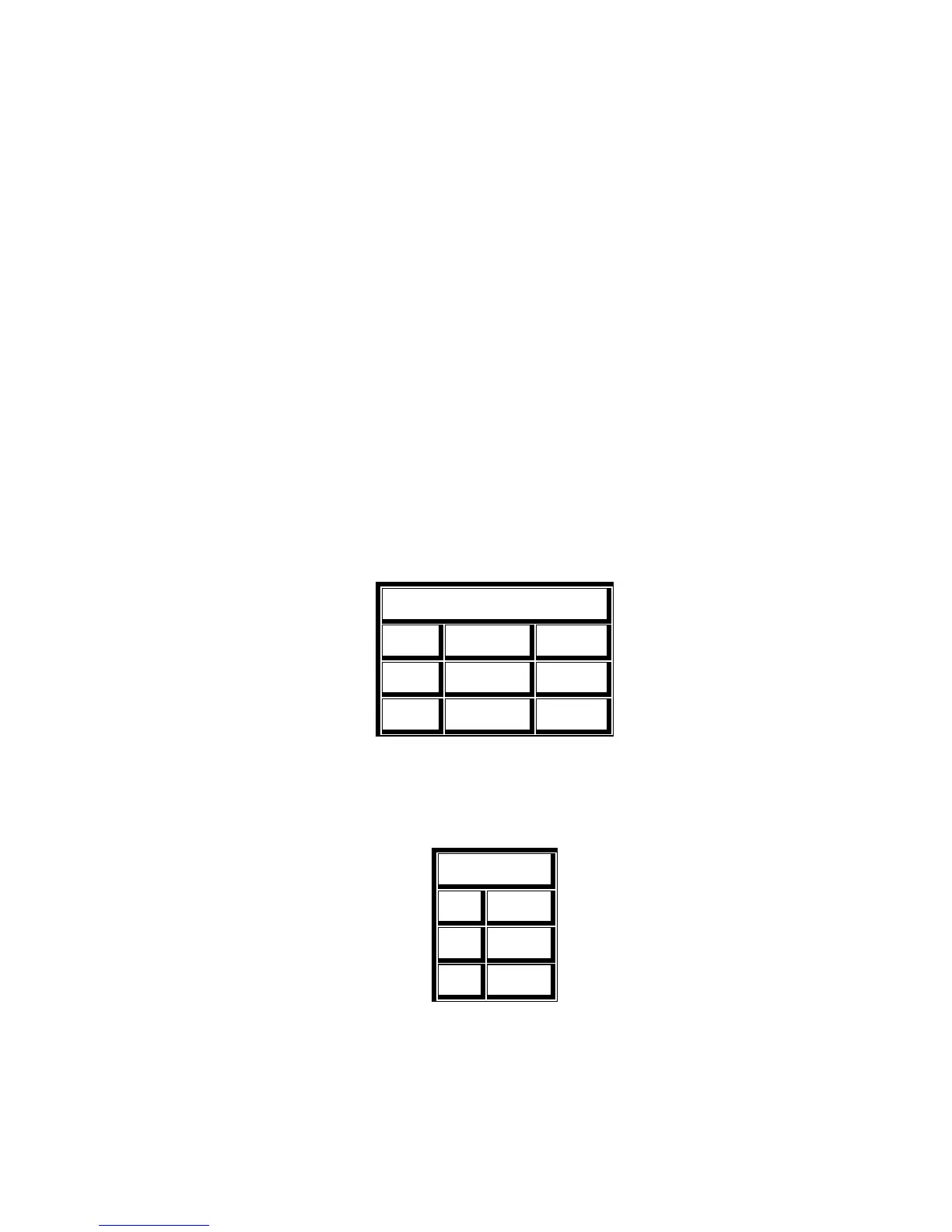
Table 5
PORT TRIMPOT TESTPOINT
1
"Port1 Disc" TP1
2
"Port2 Disc" TP2
3
"Port3 Disc" TP3
Once the receiver levels are adjusted, it's time to adjust the transmitter audio levels. While still generating a signal on the
receiver frequency, adjust the corresponding trimpot for +/- 3 Khz of the appropriate transmitter.
Table 6
PORT TRIMPOT
1
"P1 Tx"
2
"P2 Tx"
3
"P3 Tx"
Using a radio equipped with a DTMF pad, transmit on the receiver frequency and while transmitting a DTMF tone (it is
suggested you use either a "3" or a "5" for this adjustment, as these are the most difficult tones to decode. The corresponding
LED should light with every DTMF key press.
 Loading...