9
DTMF Decoders
Each port has its own dedicated DTMF decoder, with each decoder being connected full time to its respective port. DTMF may
be entered at any time from any port without regard to activity on the other ports. The controller will store the commands and act
on them in the order they were received. Each decoder may be configured to require CTCSS in order to function or not require
CTCSS.
Indicator LEDs
LED's are provided for monitoring all the Port's COS, CTCSS, PTT and Valid DTMF signals. These can be useful for setting up
and verifying operation of these various signals and are marked directly on the PC board. In order to reduce power
consumption when the LEDs do not have to be powered up, the push-on jumper on JP13 may be removed. If mounting the
RC210 in a cabinet, a switch may be connected to JP13 to allow the operator to conveniently turn the LEDs on and off as
needed.
Auxiliary Audio Inputs
These inputs allow you to add external audio devices without using one of the radio ports. For example, you could connect a
weather receiver to one and be able to monitor weather conditions on demand. If the weather receiver has an output that is
triggered when a S.A.M.E. Alert is issued, you can use one of the Alarm inputs on the RC210 to automatically trigger one (or all)
of the transmitters.
The Auxiliary Audio Inputs do not provide any means for adjusting their level, so you must provide this capability in your
interface between your audio source and the RC210. The impedance of these inputs is approximately 20K and the level should
be adjusted to approximately 100 mv peak-to-peak.
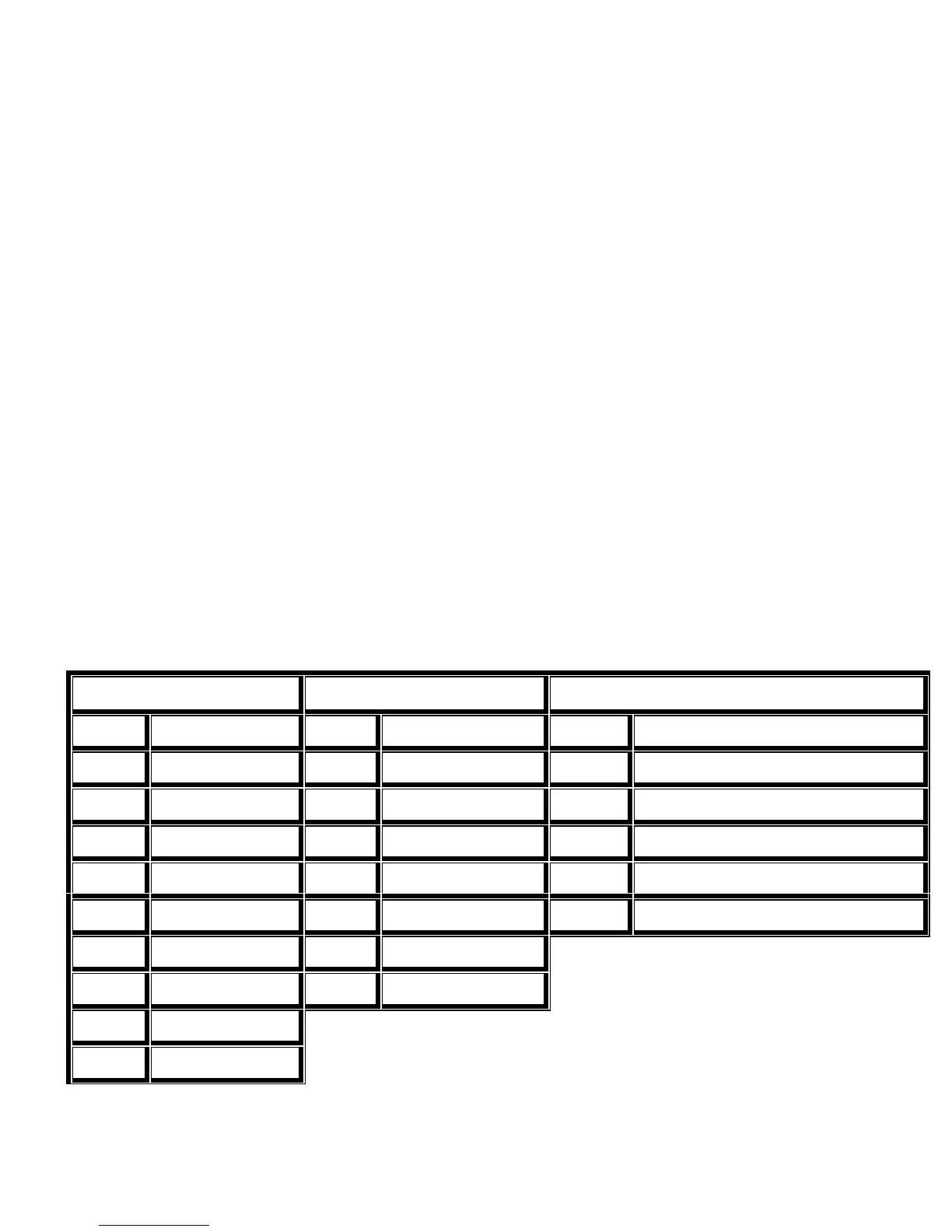
Expansion Connectors
There are several pin header connectors on the PC board which allow for easy access to several data lines in the RC210.
J8 - DTMF EXPAND J7 - I/0 EXPAND J9 - AUDIO EXPAND
Pin 1 BCD Output Q1 Pin 1 Shift Register Data Pin 1 Digital Gnd
Pin 2 BCD Output Q2 Pin 2 Shift Register Clock Pin 2 Vcc (+5)
Pin 3 BCD Output Q4 Pin 3 Shift Register Latch Pin 3 Record input to ISD
Pin 4 BCD Output Q8 Pin 4 LED Serial Data Pin 4 Auxiliary Audio Input 3
Pin 5 Decoder Strobe Port 1 Pin5 LED Data Pin 5 Auxiliary Audio Input 2
Pin 6 Decoder Strobe Port 2 Pin 6 LED Clock Pin 6 Auxiliary Audio Input 1
Pin 7 Decoder Strobe Port 3 Pin 7 Vcc (+5 Vdc)
Pin 8 Decoder Select Port 1 Pin 8 Digital Ground
Pin 9 Decoder Select Port 2
Pin 10 Decoder Select Port 3