15
Logic Outputs
The RC210 provides 7 general purpose outputs (expandable to 32) that you can use to switch electronic devices on and off at
your repeater site. While these outputs are buffered by open collector transistors, care should be used so as not to exceed their
ratings (90V dc @ 500 ma). If you're switching an inductive load, be sure to use a quenching diode
across it. If you need more
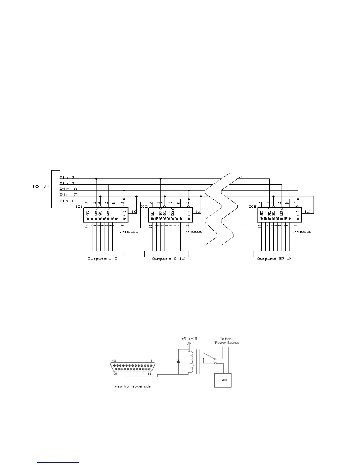
logic outputs, you can connect external shift registers and obtain up to 32 outputs. Fig 1 shows how this can be accomplished.
Only some of the stages needed to recover those functions have to be used. Each shift register used adds 8 outputs. So if you
only need an additional 16 outputs (above and beyond the 7 "on-board" outputs), you only need add 2 stages. If you want all
additional 64, you'll need a total of 8 shift registers (74HC595). Remember that these outputs are logic level and cannot drive
loads.
The outputs of the shift registers cannot drive outside devices directly. You will need some kind of driver in order to drive other
than TTL level devices. When an output of the shift register is selected by command, that output goes to a logic high. A good
option would be to use a ULN2003A Darlington array transistor array, which can drive up to half an amp (500 ma) load at a
voltage of up to 90vdc.
Fan Output
The controller also provides a switched fan output that can be used to control a cooling fan for the repeater transmitter. To avoid
unnecessary wear and tear on the fan, the fan only comes on when any transmitter is keyed, and remains on for 1 to 60 minutes
after the last transmitter drops. The amount of time the fan remains on is selected in programming mode.
This output is not meant to drive a fan directly, but rather an external relay or driver transistor which is then used to drive the fan.
Its signal is available on Pin 22 of J4, the I/0 connector. When active, the Fan Output is pulled to ground. This output is an open
collector therefore it will not source any voltage.
 Loading...