39
MD1137
19. Rotate the crankshaft until the first cap screw (from
step 17) securing the sprocket to the camshaft can be
addressed; then tighten to 11 ft-lb. Bend the tab to
secure the cap screw.
20. Install the cylinder head plug with the cupped end
facing the camshaft and the opening directed down-
wards.
21. Place the cam chain tensioner assembly and gasket
into the cylinder. Tighten to 10 ft-lb.
22. Using a flat-blade screwdriver, turn the tensioner
screw counterclockwise to apply tension to the cam
chain; then install the cap screw plug and washer and
tighten securely.
FI608
23. Loosen the adjuster screw jam nuts; then loosen the
adjuster screws on the rocker arms in the valve
cover.
24. Apply a thin coat of Three Bond Sealant to the mat-
ing surface of the valve cover; then place the valve
cover into position. Note that the two alignment pins
are properly positioned.
NOTE: At this point, the rocker arms and adjuster
screws must not have pressure on them.
25. Install the four top-side cap screws with rubber
washers; then install the remaining cap screws.
Tighten only until snug.
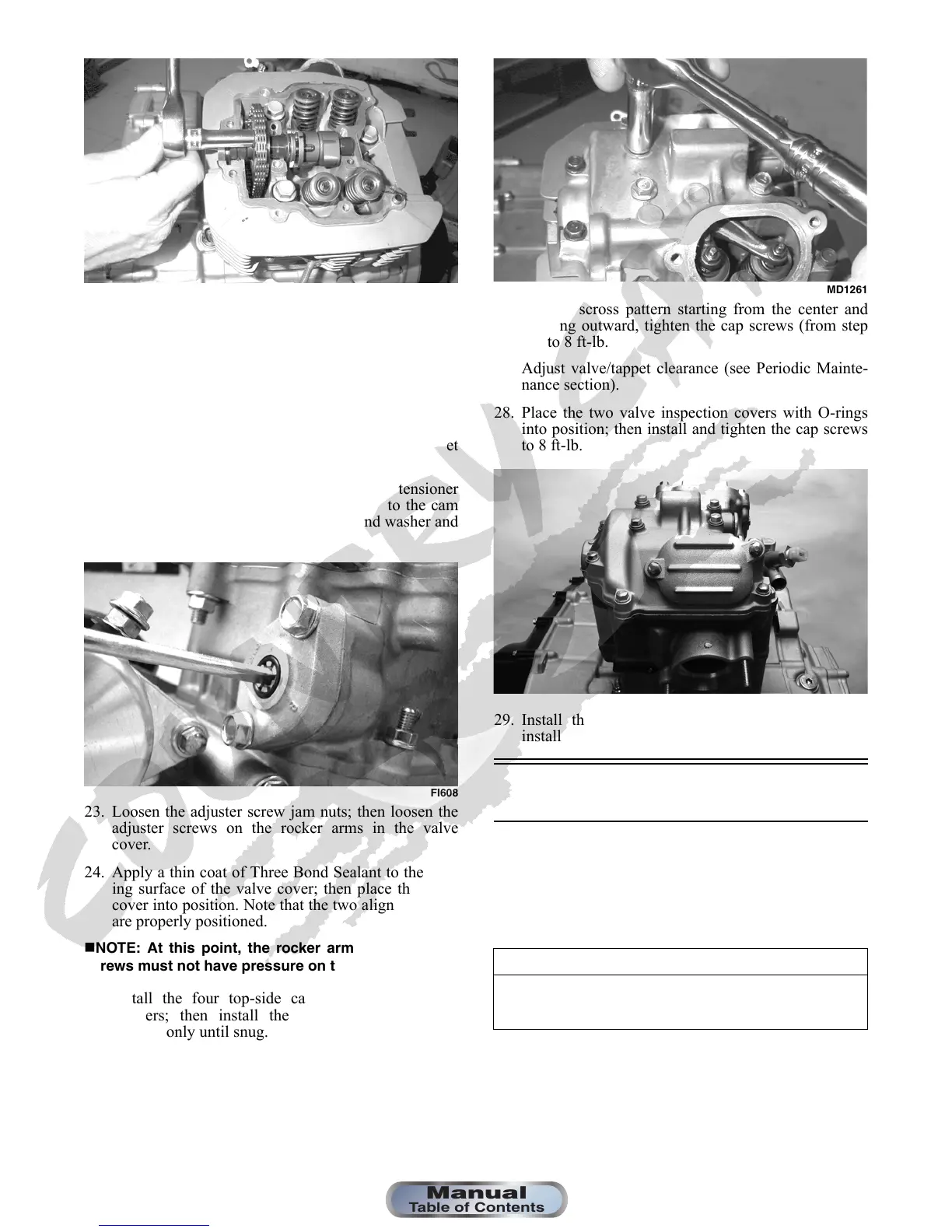
MD1261
26. In a crisscross pattern starting from the center and
working outward, tighten the cap screws (from step
25) to 8 ft-lb.
27. Adjust valve/tappet clearance (see Periodic Mainte-
nance section).
28. Place the two valve inspection covers with O-rings
into position; then install and tighten the cap screws
to 8 ft-lb.
FI602
29. Install the spark plug and tighten securely; then
install the timing inspection plug.
Left-Side Components
NOTE: For efficiency, it is preferable to remove and
disassemble only those components which need to
be addressed and to service only those components.
The technician should use discretion and sound
judgment.
NOTE: The engine/transmission does not have to
be removed from the frame for this procedure.
AT THIS POINT
To service any one specific component, only limited dis-
assembly of components may be necessary. Note the
AT THIS POINT information in each sub-section.







 To Next Page