8
void setup() // one-time actions
{
pinMode(2,OUTPUT); // define pin 2 as an output
}
void loop() // loop forever
{
digitalWrite(2,HIGH); // pin 2 high (LED on)
delay(500); // wait 500 ms
digitalWrite(2,LOW); // pin 2 low (LED off)
delay(500); // wait 500 ms
}
The pinMode command sets the LED pin to be an output. The first digitalWrite command says to
set pin 2 of the Arduino to HIGH, or +5 volts. This sends current from the pin, through the
resistor, through the LED (which lights it) and to ground. The delay(500) command waits for
500 msec. The second digitalWrite command sets pin 2 to LOW or 0 V stopping the current
thereby turning the LED off. Code within the brackets defining the loop() function is repeated
forever, which is why the LED blinks.
This exercise shows how the Arduino can control the outside world. With proper interface
circuitry the same code can turn on and off motors, relays, solenoids, electromagnets, pneumatic
valves or any other on-off type device.
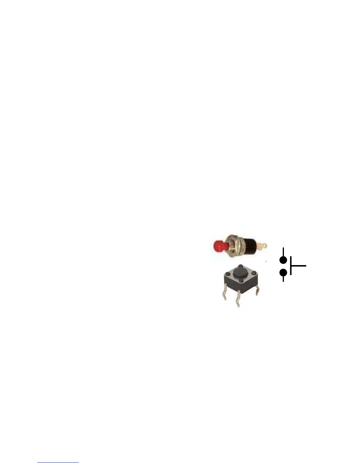
3 Reading a switch
The LED exercise shows how the Arduino can control
the outside world. Many applications require reading the
state of sensors, including switches. The figure to the
right shows a picture of a pushbutton switch and its
schematic symbol. Note that the symbol represents a
switch whose contacts are normally open, but then are
shorted when the button is pushed. If you have a switch,
use the continuity (beeper) function of a digital multi-
meter (DMM) to understand when the leads are open and
when they are connected as the button is pushed.
For this exercise, the Arduino will read the state of a normally-open push button switch and
display the results on the PC using the serial.println() command. You will need a switch, a 10
kohm resistor and some pieces of 22 g hookup wire. If you don't have a switch, substitute two
wires and manually connect their free ends to simulate a switch closure. The figure below shows
the schematic for the circuit on the left and a realization on the right.

 Loading...