P92x/EN FT/E11 Technical Guide
User Guide
Page 28/110 MiCOM P921-P922-P923
7.6 “CONFIGURATION INPUTS” sub-menu
This menu allows the user to configure the operation of the logic inputs ; either on
falling edge/low level or on rising edge/high level. When selecting 1, the logic input
becomes active when it is excited or energized, and inactive when it is de-energized.
This menu allows also the selection of the type of the auxiliary voltage signal to be
applied to the logic inputs.
To gain access to the "CONFIGURATION INPUTS" menu from the default display,
press 2 once, 6 once, 2 once and 6 4 times (P921) or 5 times (P922) or 6 times
(P923).
7.6.1 HMI description
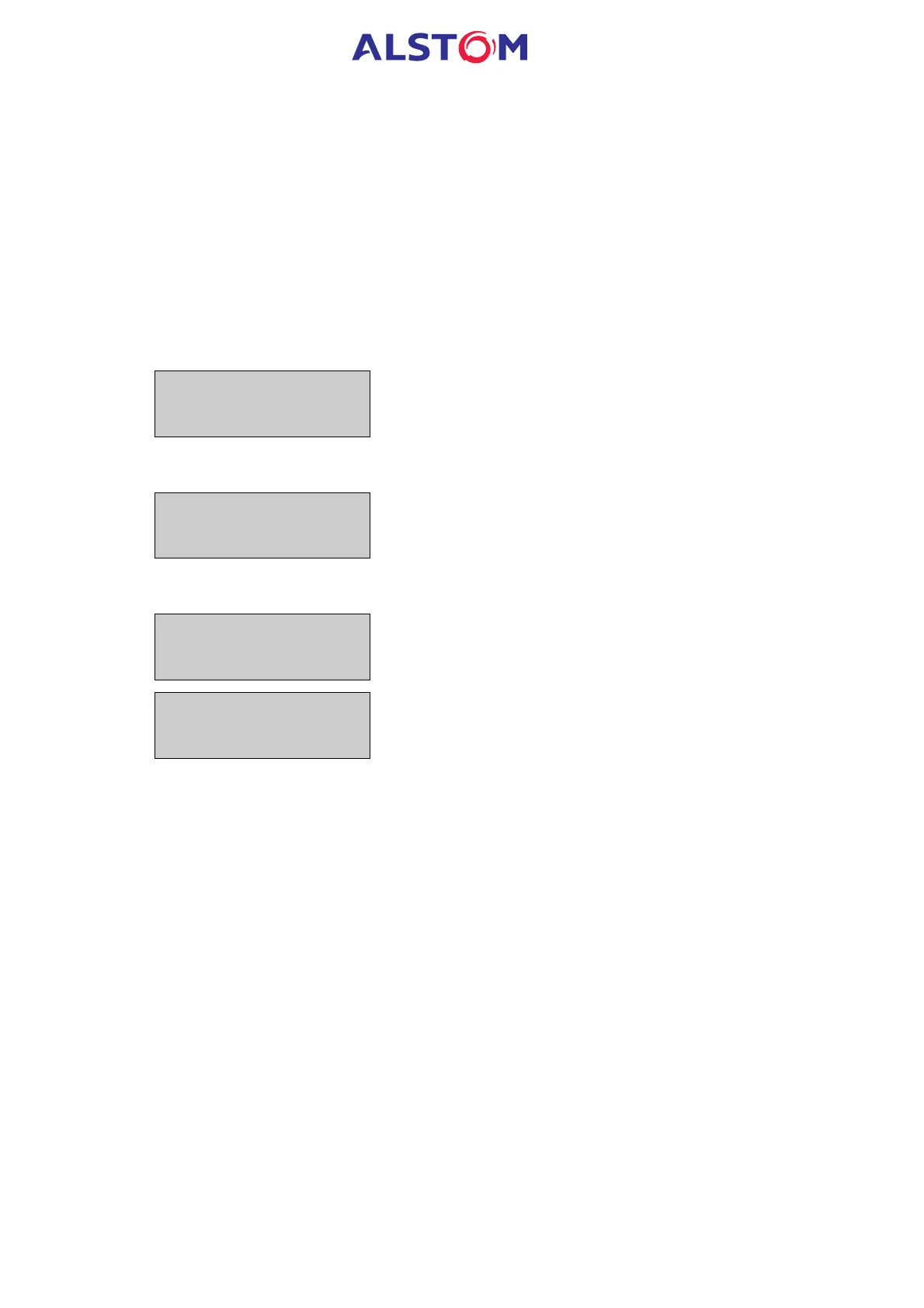
CONFIGURATION
INPUTS
Heading of "CONFIGURATION INPUT
· MiCOM P921
INPUTS : 21
11
Description : configuration of the all logic inputs
Range : 0 or 1
· MiCOM P922 P923
INPUTS : 54321
11111
Description : configuration of the all logic inputs
Range : 0 or 1
VOLTAGE INPUTS =
DC
Description : selection of the type of the input voltage applied
to the logic inputs.
Range : DC or AC
NOTE : with version V4 software and V3 hardware, the setting of the
VOLTAGE INPUT should be DC.