Technical Guide P92x/EN CM/E11
Commissioning Guide
MiCOM P921-P922-P923 Page 11/28
abcd
4.2.3 Light Emitting Diodes (LEDs)
On power up the green LED should have illuminated and stayed on indicating that
the relay is healthy. The relay has non-volatile memory which remembers the state
(on or off) of the alarm and trip LEDs when the relay was last energised from an
auxiliary supply. Therefore these indicators may also illuminate when the auxiliary
supply is applied.
If any of these LEDs are on then they should be reset before proceeding with further
testing. If the LEDs successfully reset (the LED goes out), there is no testing required
for that LED because it is known to be operational.
4.2.3.1 Testing the alarm LED
To do this, activate the "Undervoltage" function, 1
st
stage.
If there is no voltage across the VT inputs, the "alarm" LED begins to flash and a
message appears on the front panel.
4.2.3.2 Testing the trip LED
Repeat the previous test and allocate the time-delayed information (tV<) to the trip
relay. Check that the trip LED has illuminated.
4.2.3.3 Testing the user-programmable LEDs
Repeat the previous test and allocate the instantaneous information (V<) to LED 5,
then to LEDs 6, 7 and 8. Check that each LED has illuminated.
4.2.4 Opto-isolated inputs
This test checks that all the opto-isolated inputs on the relay are functioning correctly.
(2 opto-isolated inputs for the P921 and 5 opto-isolated inputs for the P922 and
P923).
The opto-isolated inputs should be energised one at a time. Ensuring correct polarity,
connect the auxiliary voltage to the appropriate terminals for the input being tested.
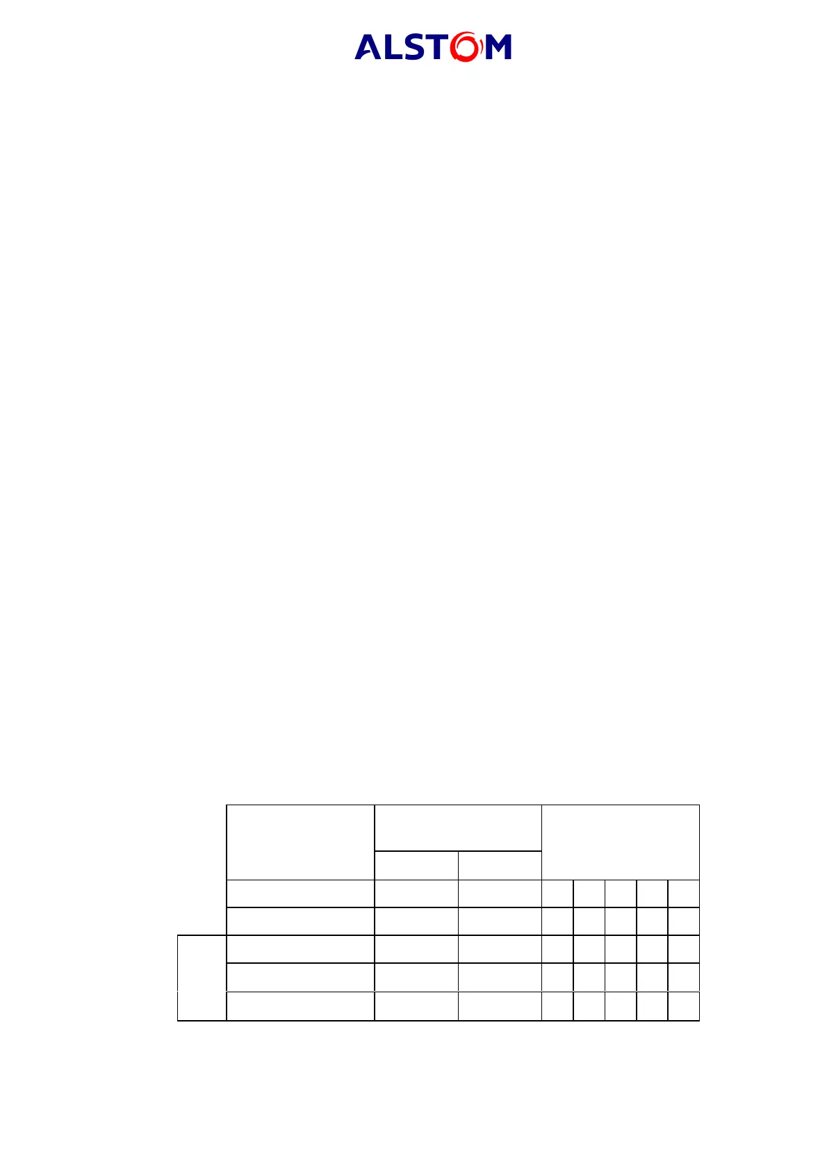
The opto-isolated input terminal allocations are given in Table 3.
The line "INPUTS" in the "OP. PARAMETERS" menu gives the state of each input, a '1'
indicating an energised input and a '0' indicating a de-energised input. When each
input is energised one of the digits on the bottom line of the display will change to the
value shown in Table 3 to indicate the new state of the inputs.
Apply a continuous
voltage across terminals
Inputs
negative positive
Inputs
Opto input 1 24 22 00001
Opto input 2 28 26 00010
Opto input 3 19 17 00100
Opto input 4 23 21 01000
P922-P923
Opto input 5 27 25 10000
TABLE 3 : OPTO-ISOLATED INPUT TERMINALS