Technical Guide P92x/EN CM/E11
Commissioning Guide
MiCOM P921-P922-P923 Page 13/28
abcd
4.2.6 Rear communications port
This test should only be performed where the relay is to be accessed from a remote
location and will vary depending on the communications standard being adopted.
It is not the intention of the test to verify the operation of the complete system from the
relay to the remote control centre, just the relay's rear communications port and any
protocol converter necessary.
The protocol available for remote communication appears on the label on the relay
front panel (under the top cover).
4.2.6.1 Courier communications
If a K-Bus to RS232 KITZ protocol converter is installed, connect a portable PC
running the appropriate software to the incoming (remote from relay) side of the
protocol converter.
If a KITZ protocol converter is not installed, it may not be possible to connect the PC
to the type installed. In this case a KITZ protocol converter and portable PC running
appropriate software should be temporarily connected to the relay’s K-Bus port. The
terminal numbers for the relay’s K-Bus port are given in Table 5. However, as the
installed protocol converter is not being used in the test, only the correct operation of
the relay’s K-Bus port will be confirmed.
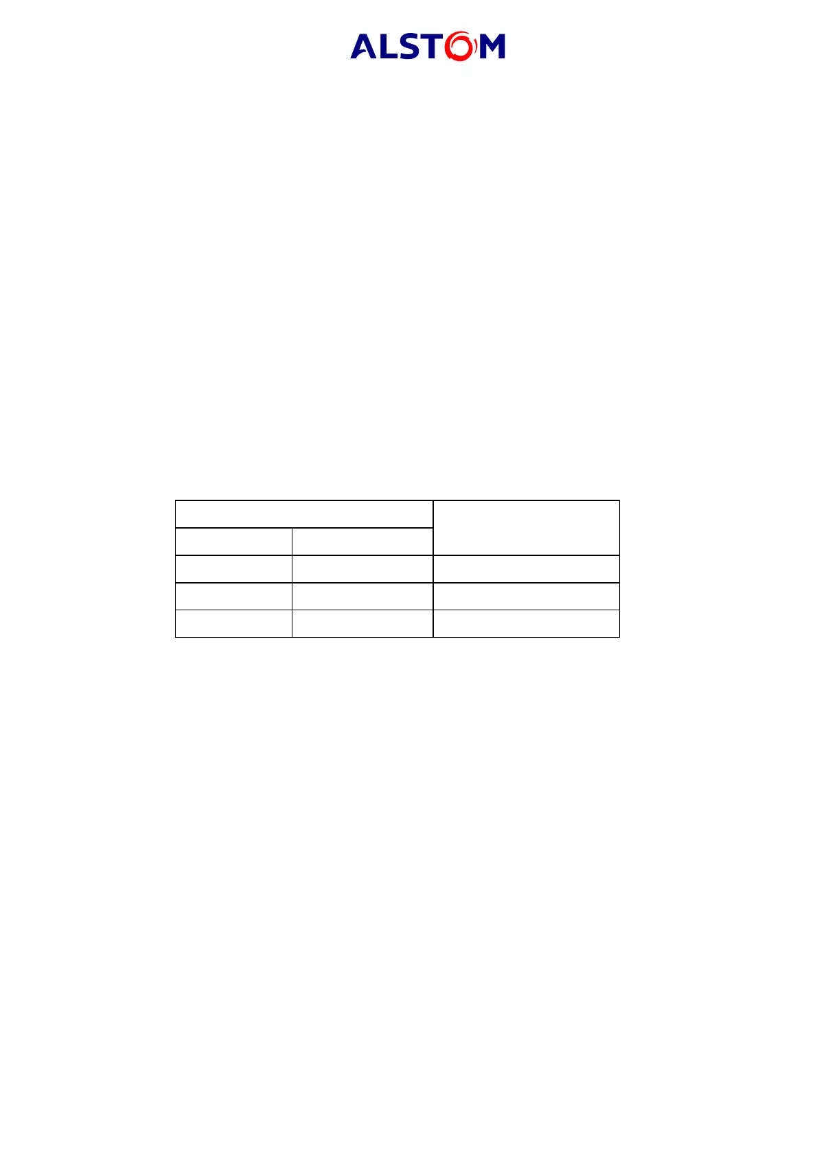
Connection Terminal
KBUS Modbus or VDEW
Screen Screen 30
1 positive 31
2negative32
TABLE 5 : RS485 TERMINALS
The relay's Courier address in the "COMMUNICATIONS" menu must be set to a value
between 1 and 255.
Check that communications can be established with this relay using the portable PC.
4.2.6.2 Modbus communications
Connect a portable PC (“master station”) running the appropriate Modbus Master
Station software to the relay’s RS485 port via a RS485 to RS232 interface converter.
The terminal numbers for the relay’s RS485 port are given in Table 5.
Ensure that the relay address, baud rate and parity settings in the Modbus software
are set the same as on the MiCOM relay (see "COMMUNICATIONS" menu).
Check that communications with this relay can be established.
4.2.6.3 IEC60870-5-103 (VDEW) communications
IEC60870-5-103/VDEW communication systems are designed to have a local Master
Station. This should be used to verify that the relay's fibre optic or RS485 port, as
appropriate, is working.
Ensure that the relay address, baud rate and parity settings in the Master Station
software are set the same as on the MiCOM relay (see "COMMUNICATIONS" menu).
Check that, using the Master Station, communications with the relay can be
established.