P92x/EN CM/E11 Techncal Guide
Commissioning Guide
Page 16/28 MiCOM P921-P922-P923
abcd
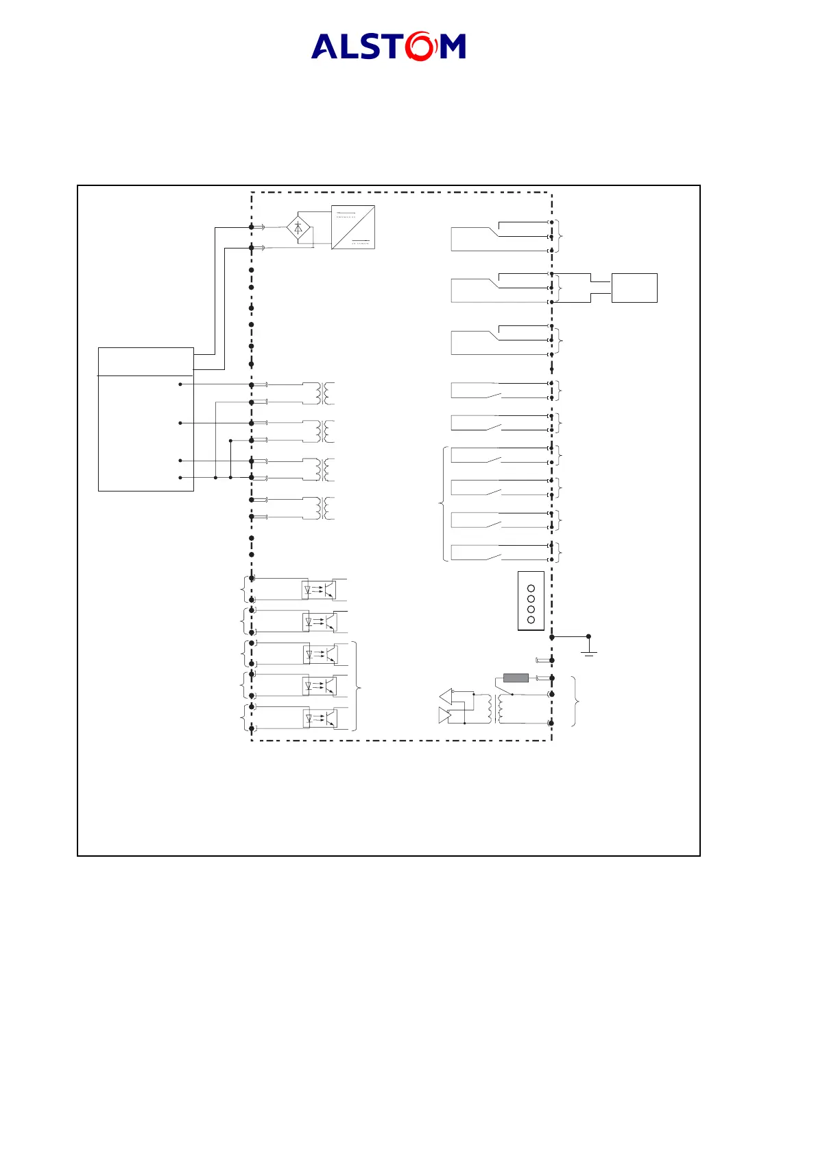
5.3 Testing the "Phase overvoltage protection" and "Phase undervoltage
protection" functions
5.3.1 Wiring diagram
33
34
+
_
+
_
Notes :
(1) Supplementary hardware for MiCOM P922-P923 relay
(2) Supplementary hardware for MiCOM P922-P923 relay
(3) 3VT assembly, Phase-Neutral
41
A
B
C
N
42
43
44
45
46
49
50
22
24
26
28
19
17
21
23
27
25
WD
37
35
36
RL1
6
4
2
RL2
12
10
8
29
31
32
-
30
*
+
_
EL1
Auxiliary
power supply
Auxiliary
power supply
Watchdog
RL3
16
14
RL4
20
18
RL5
3
1
RL6
7
5
RL7
9
11
RL8
13
15
4 programmable
LEDs
Case earth
RS 485
communication port
(Modbus, Courier,
CEI60870-5-103)
*
(* For the last relay
of the RS 485 link,
connect terminal 30 to terminal 32)
LEDs
See note 2
See note 1
See note 3
MiCOM P92
*
RL1
RL2
RL3
EL2
EL3
EL4
EL5
RL4
RL5
RL6
RL7
RL8
P0408ENa
Stop
chrono
Voltage
source
FIGURE 2 : (V>) AND (V>>) STAGE TEST