Technical Guide P92x/EN CO/E11
Connection Diagrams
MiCOM P921-P922-P923 Page 9/10
aB
2.2 RS485 rear port
2.2.1 Description
The rear RS485 interface is isolated and is suitable for permanent connection
whichever protocol is selected. The advantage of this type of connection is that up to
31 relays can be ‘daisy chained’ together using a simple twisted pair electrical
connection.
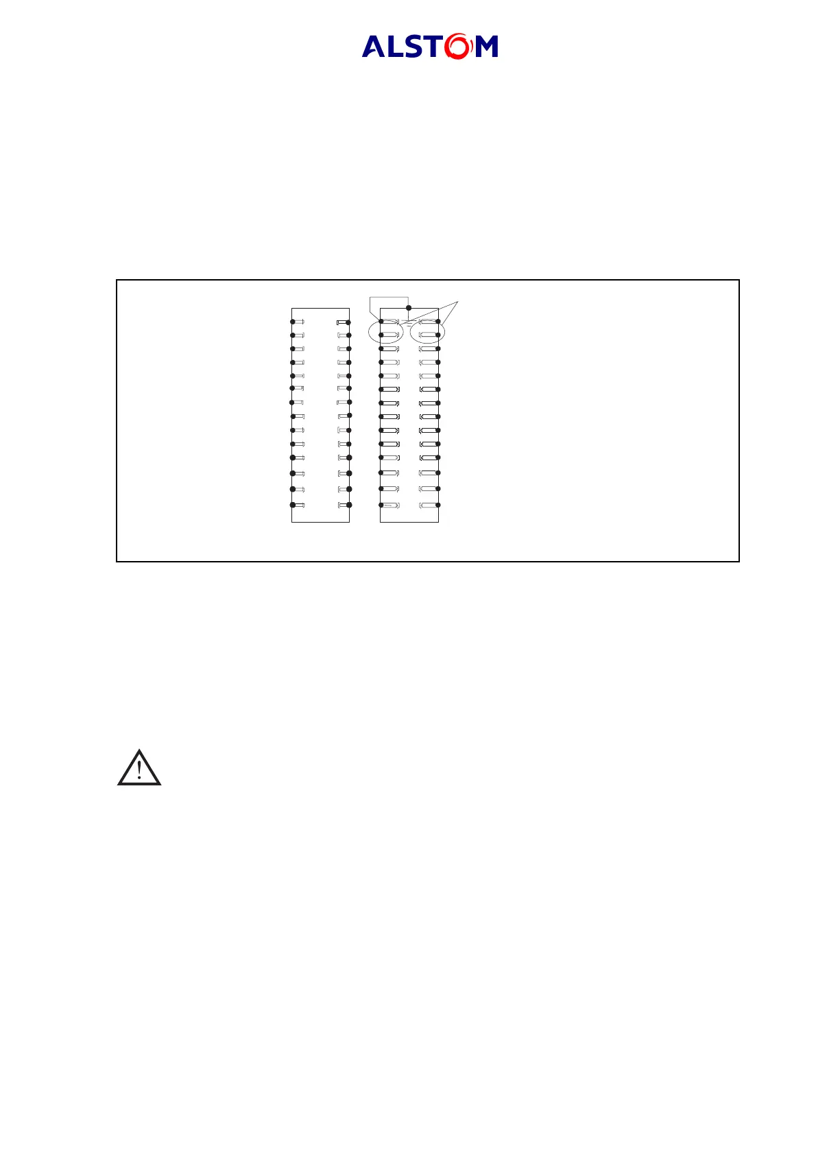
2.2.2 Connection
30
32
34
36
38
40
42
44
46
48
50
52
54
56
29
31
33
35
37
39
41
43
45
47
49
51
53
55
4
6
8
10
18
20
1
3
5
7
9
1413
17
19
22
24
26
28
21
23
25
27
1615
12
11
2
Rear terminals
Communication
connections
P0180ENa
FIGURE 7 : RS485 CONNECTION
The total communication cable from the master unit to the farthest slave device is a
spur, and no branches may be made from this spur. The maximum cable length is
1000m and the maximum number of devices per spur is 32.
The transmission wires should be terminated using a 150 W resistor at both extreme
ends of the cable. To do this, connect the terminals 30 and 32 together.
Polarity is not necessary for the 2 twisted wires.
WARNING : TERMINALS F33 AND F34 ARE USED FOR THE POWER SUPPLY. DO NOT
CONNECT THE VOLTAGE POWER SUPPLY TO TERMINALS F31 AND F32.
2.2.3 Convertors
2.2.3.1 Protocol convertor : RS232 -> K-Bus
KITZ 101,102 and 201 can be used.
Configuration is : 19200 bauds, 11 bits, full duplex.
2.2.3.2 RS232 / RS485 converter
The following RS232/RS485 converters have been tested by AREVA :
RS_CONV1 : convertor suitable for a short length and for
up to 4 connected relays
RS_CONV32 : industrial convertor, suitable for up to 31
connected relays.