P92x/EN CO/E11 Technical Guide
Connection Diagrams
Page 8/10 MiCOM P921-P922-P923
aB
2. PORTS CONNECTION
2.1 Front port connection (RS232)
The front communication port is provided by a 9-pin female D-type connector located
under the bottom hinged cover. It provides RS232 serial data communication
(asynchronous RS232 connection according the IEC870 requirements) and is
intended for use with a PC locally to the relay (up to 15m distance).
The relay is a Data Communication Equipment (DCE) device. Thus the pin
connections of the relay’s 9-pin front port are as follows:
Pin no. 2 Tx Transmit data
Pin no. 3 Rx Receive data
Pin no. 5 0V Zero volts common
None of the other pins are connected in the relay. The relay should be connected to
the serial port of a PC, usually called COM1 or COM2. PCs are normally Data
Terminal Equipment (DTE) devices which have a serial port pin connection as below
(if in doubt check your PC manual):
Pin no. 2 Rx Receive data
Pin no. 3 Tx Transmit data
Pin no. 5 0V Zero volts common
For successful data communication, the Tx pin on the relay must be connected to the
Rx pin on the PC, and the Rx pin on the relay must be connected to the Tx pin on the
PC, as shown in figure 5. Therefore, providing that the PC is a DTE with pin
connections as given above, a ‘straight through’ serial connector is required, i.e. one
that connects pin 2 to pin 2, pin 3 to pin 3, and pin 5 to pin 5. Note that a common
cause of difficulty with serial data communication is connecting Tx to Tx and Rx to Rx.
This could happen if a ‘cross-over’ serial connector is used, i.e. one that connects pin
2 to pin 3, and pin 3 to pin 2, or if the PC has the same pin configuration as the
relay.
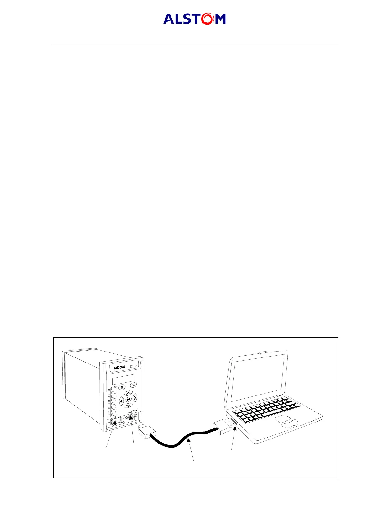
MiCOM P921 relay
Laptop
Serial communication port (COM1 or COM2)
Serial data connector (up to 15 m)
Battery
9 pin front port
P0394ENa
FIGURE 6 : PC<->RELAY SIGNAL CONNECTION