Technical Guide P92x/EN TD/E11
Technical Data
MiCOM P921-P922-P923 Page 15/30
3.3 Residual overvoltage / neutral displacement (ANSI code 59N)
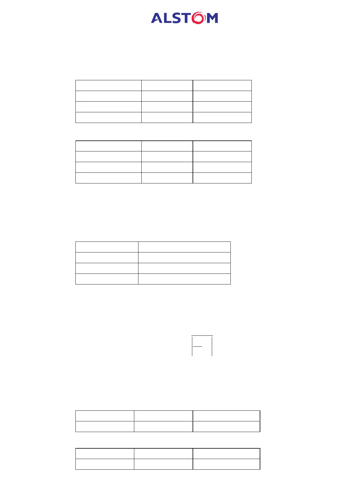
3.3.1 Threshold settings (secondary values)
- Nominal voltage range : 57 – 130V
Setting Range Step Size
V
0
> Voltage set 0.5 – 130V 0.1V
V
0
>> Voltage set 0.5 – 130V 0.1V
V
0
>>> Voltage set 0.5 – 130V 0.1V
- Nominal voltage range : 220 – 480V
Setting Range Step Size
V
0
> Voltage set 2 – 480V 0.5V
V
0
>> Voltage set 2 – 480V 0.5V
V
0
>>> Voltage set 2 – 480V 0.5V
3.3.2 Time delay settings
Each voltage element is associated to an independent time delay.
Each measuring element time delay can be blocked by the operation of a user
defined logic (optical isolated) input (see “Blocking logic1” or “Blocking logic2”
functions).
Element Time delay type
1
st
stage Definite Time (DT) or IDMT
2
nd
stage DT
3
rd
stage DT
3.3.3 Inverse Time Delay Characteristic
The inverse characteristic is defined by the following formula :
÷
÷
÷
÷
÷
ø
ö
ç
ç
ç
ç
ç
è
æ
-
=
1
V
V
TMS
t
S
0
where :
t = operating time in seconds
TMS = time Multiplier Setting
V
0
= applied input voltage
Vs = relay setting voltage
Setting Range Step Size
TMS 0,5 - 100 0.5
Setting Range Step Size
TRESET (only DT) 0 – 100s 0.01s