P92x/EN TD/E11 Technical Guide
Technical Data
Page 16/30 MiCOM P921-P922-P923
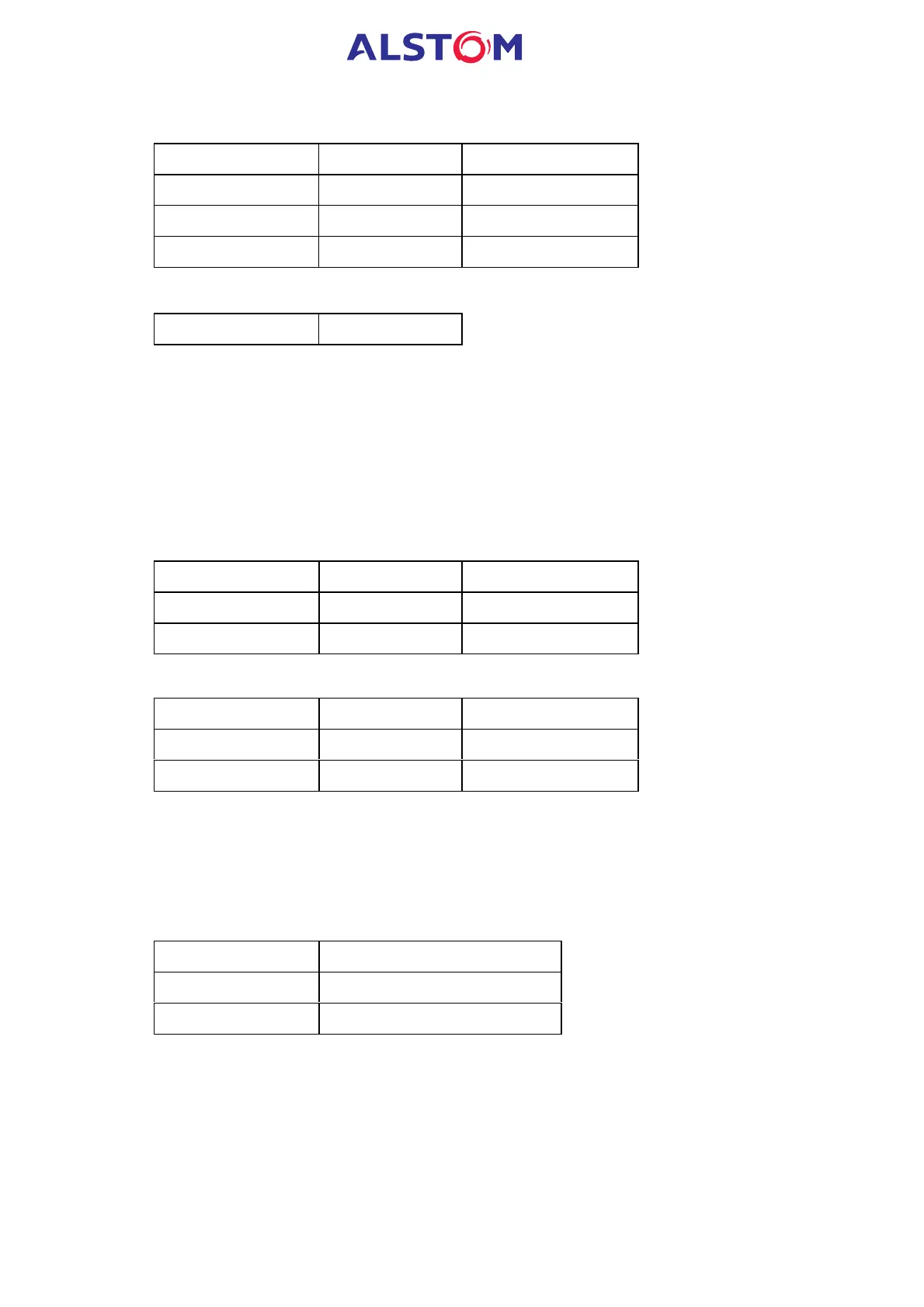
3.3.4 Definite time delay characteristics
Setting Range Step Size
tV
0
> 0 – 599s 0.01s
tV
0
>> 0 – 599s 0.01s
tV
0
>>> 0 – 599s 0.01s
3.3.5 Hysteresis
Hysteresis fixed 95%
(see § 9.3 Protection accuracy)
When the V
0
> is associated with IDMT curve, the recommended maximum setting
value should be less or equal to max. withstand voltage of the VT inputs divided by
20.
3.4 Negative sequence overvoltage (ANSI code 47) only P922 & P923
3.4.1 Threshold settings (secondary values)
- Nominal voltage range : 57 – 130V
Setting Range Step Size
V
2
> Voltage set 5 – 200V 0.1V
V
2
>> Voltage set 5 – 200V 0.1V
- Nominal voltage range: 220 – 480V
Setting Range Step Size
V
2
> Voltage set 20 – 720V 0.5V
V
2
>> Voltage set 20 – 720V 0.5V
3.4.2 Time delay settings
Each voltage element is associated to an independent time delay.
Each measuring element time delay can be blocked by the operation of a user
defined logic (optical isolated) input (see “Blocking logic1” or “Blocking logic2”
functions).
Element Time delay type
1
st
stage Definite Time (DT) or IDMT
2
nd
stage DT