Technical Guide P92x/EN FT/E11
User Guide
MiCOM P921-P922-P923 Page 7/110
2.1 Menu structure
Frequency
Date and time
3 phase voltage
Alarm
messages
Other
default displays
Column 1
OP Parameters
Column 2
Configuration
Column n
Protection G1
Data 1.1
Password
Sub-menu
"General"
Sub-menu
"UNDERVOLTAGE"
Other setting
cells in column 1
P0398ENa
Other column headings
Data 1.2
Model n˚
Data 2.1
Connection
Data n.2-
V<=
Data n.n-
V<<<
Data 1.n
Relays status
Data 2.n
Default display
Other setting
cells in column 2
Other setting
cells in column n
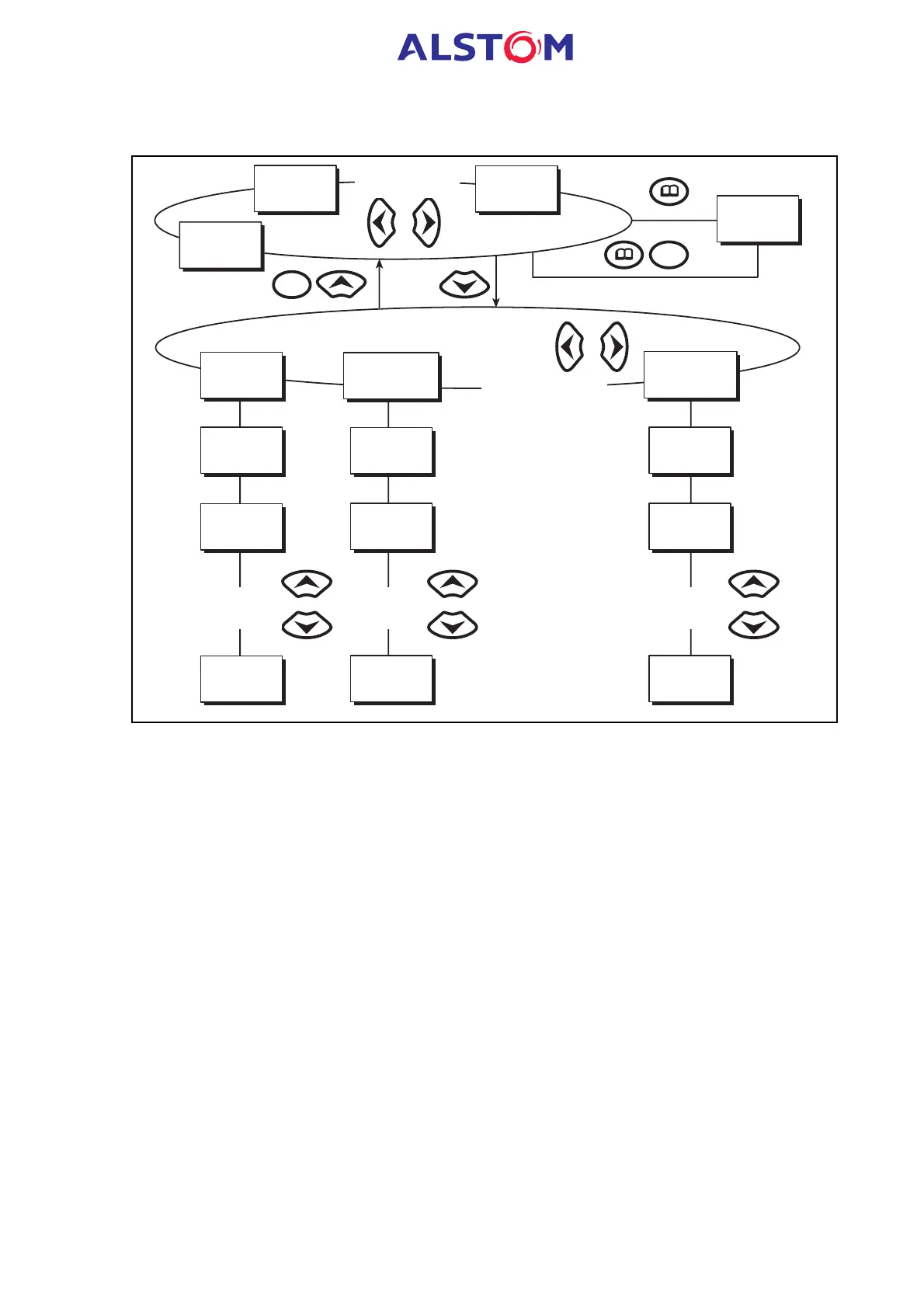
FIGURE 1 : STRUCTURE MENU
The relay’s menu is arranged in a tabular structure. Each setting in the menu is
referred to as a cell, and each cell in the menu is accessed by reference to a row and
column address. The settings are arranged so that each column contains related
settings. As shown in Figure 1, the top row of each column contains the heading
which describes the settings contained within that column. Movement between the
columns of the menu can only be made at the column heading level.
2.2 Password protection
The password is 4 characters of upper case text. The factory default for the password
is AAAA. The password is user-changeable once it has been correctly entered. Entry
of the password is achieved either by a prompt when a setting change is attempted,
or by moving to the ‘Password’ cell in the ‘OP. PARAMETERS’ column of the menu. If
the password is lost, an emergency password can be supplied – contact AREVA with
the relay’s serial number.
2.3 Front Panel User Interface (Keypad and LCD)
When the keypad is exposed it provides full access to the menu options of the relay,
with the information displayed on the LCD.
The 2, 8, 6 and 4 keys are used for menu navigation and setting value changes.