19
When connecting each power wire to the correspond-
ing terminal, follow the instructions below and fasten
the wire securely tight with the fixing screw of the ter-
minal plate.
a) For Indoor Unit
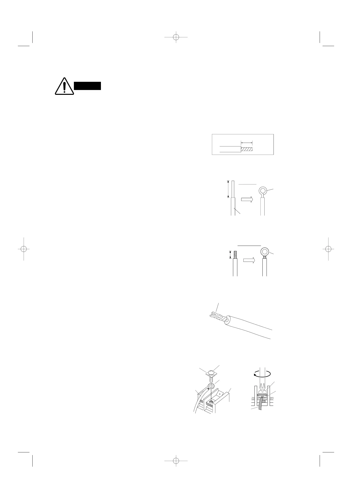
(1) Cut the wire end with a cutting pliers, then strip
the insulation to expose the wire about 7 mm. See
the label (Fig. 29) near the terminal plate.
(2) Using a screwdriver, loosen the terminal screw on
the terminal plate.
(3) Insert the wire and tighten the terminal screw
completely using a screwdriver.
b) For Outdoor Unit
■ For solid core wiring (or F-cable)
(1) Cut the wire end with a cutting pliers, then strip the
insulation to expose the solid wire about 25 mm.
(Fig. 30a)
(2) Using a screwdriver, remove the terminal screw(s)
on the terminal plate.
(3) Using the pliers, bend the solid wire to form a loop
suitable for the terminal screw.
(4) Shape the loop wire properly, place it on the termi-
nal plate and fix it securely with the removed ter-
minal screw using a screwdriver.
■ For stranded wiring
(1) Cut the wire end with a cutting pliers, then strip
the insulation to expose the stranded wiring about
10 mm and tightly twist the wire ends. (Figs. 30b
and 31a)
(2) Using a screwdriver, remove the terminal screw(s)
on the terminal plate.
(3) Using a ring connector fastener or pliers, securely
clamp each stripped wire end with a ring connec-
tor. (Fig. 30b)
(4) Place the ring connector wire, and replace and
tighten the removed terminal screw using a
screwdriver. (Fig. 31b)
 Loading...