11223312312 3
ABC
D
Attach the label
1
2
Ground
1
21 345678
1
21 345678
1
2
4
1
2
4
Indoor unit A
Outdoor unit A
Indoor unit B
Indoor unit C
BK
WR
R
R
1
2
4
BK
W
BK
W
BK
W
R
R
BK
W
R
BK
WR
A
B
C
Label A
Label B
Label C
Inter-unit cables
φ
1.0 (not provided)
Inter-unit cables
φ
1.0 (not provided)
Inter-unit cables
φ
1.0 (not provided)
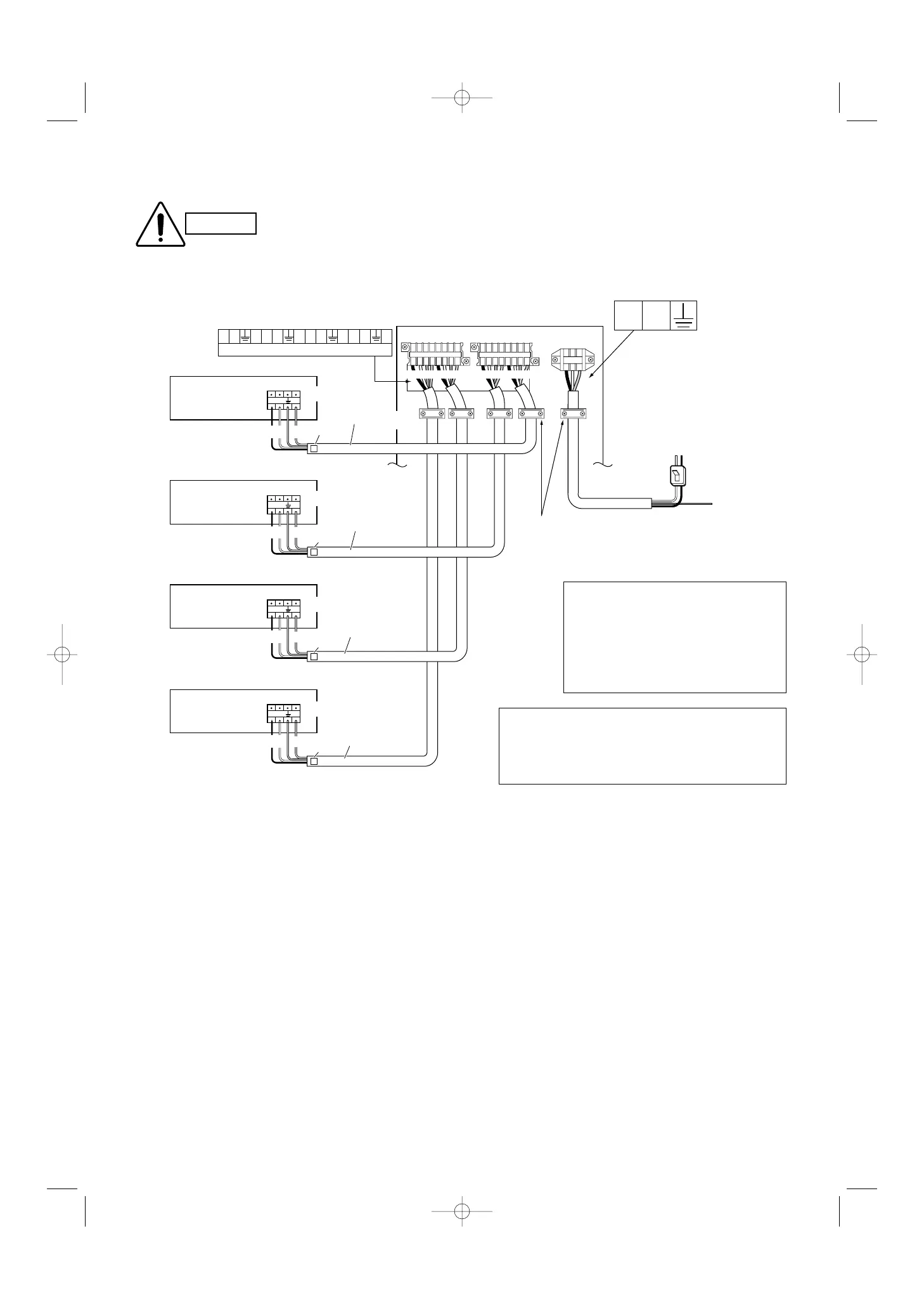
“A” is the indoor unit with
refrigerant tubing that is
connected to service valve
A (top) of the outdoor unit.
“B” is the indoor unit with
refrigerant tubing that is
connected to service valve
B (top) of the outdoor unit.
“C” is the indoor unit with
refrigerant tubing that is
connected to service valve
C (top) of the outdoor unit.
A
B
C
Fasten the
cable with cable
fasteners.
Power cable (not provided)
(
φ
2.0 mm: Less than 15 m)
(
φ
2.6 mm: Less than 20 m)
(
φ
3.5 mm: Less than 26 m)
Power:
Single-phase,
220 – 240 V
Power switch
(not provided)
Terminal board
Terminal board
Terminal board
Indoor unit D
R
1
2
4
BK
W
D
Label D
Inter-unit cables
φ
1.0 (not provided)
“D” is the indoor unit with
refrigerant tubing that is
connected to service valve
D (top) of the outdoor unit.
Terminal board
Terminal board
D
BK
W
5-6. Wiring Instructions for the Outdoor Unit
● Be sure to correctly align inter-unit cables A, B, C and D.
Be sure to perform grounding.
● Attach a ground wire to either the
outdoor unit or indoor unit.
● If there is a grounding terminal
inside the room, use the grounding
screw inside the indoor unit.
● Be sure to apply the provided labels to both
ends of the inter-unit cables to prevent mis-
wiring. The units will not function if the wiring
connections are incorrect.
● Use a dedicated A/C circuit for power.
● To make connections to the outdoor unit, remove the
inspection panel and tubing panel.
● Do not bring the inter-unit cables or power cable into
contact with tubing or service valves.
● Use outdoor unit cable fasteners and fasten the inter-
unit cables at the location where the cables are double-
sheathed.
● Arrange the wiring so that the inter-unit cables are con-
tained in the inspection panel and tubing panel, as
shown in Fig. 32.
CAUTION
 Loading...