6
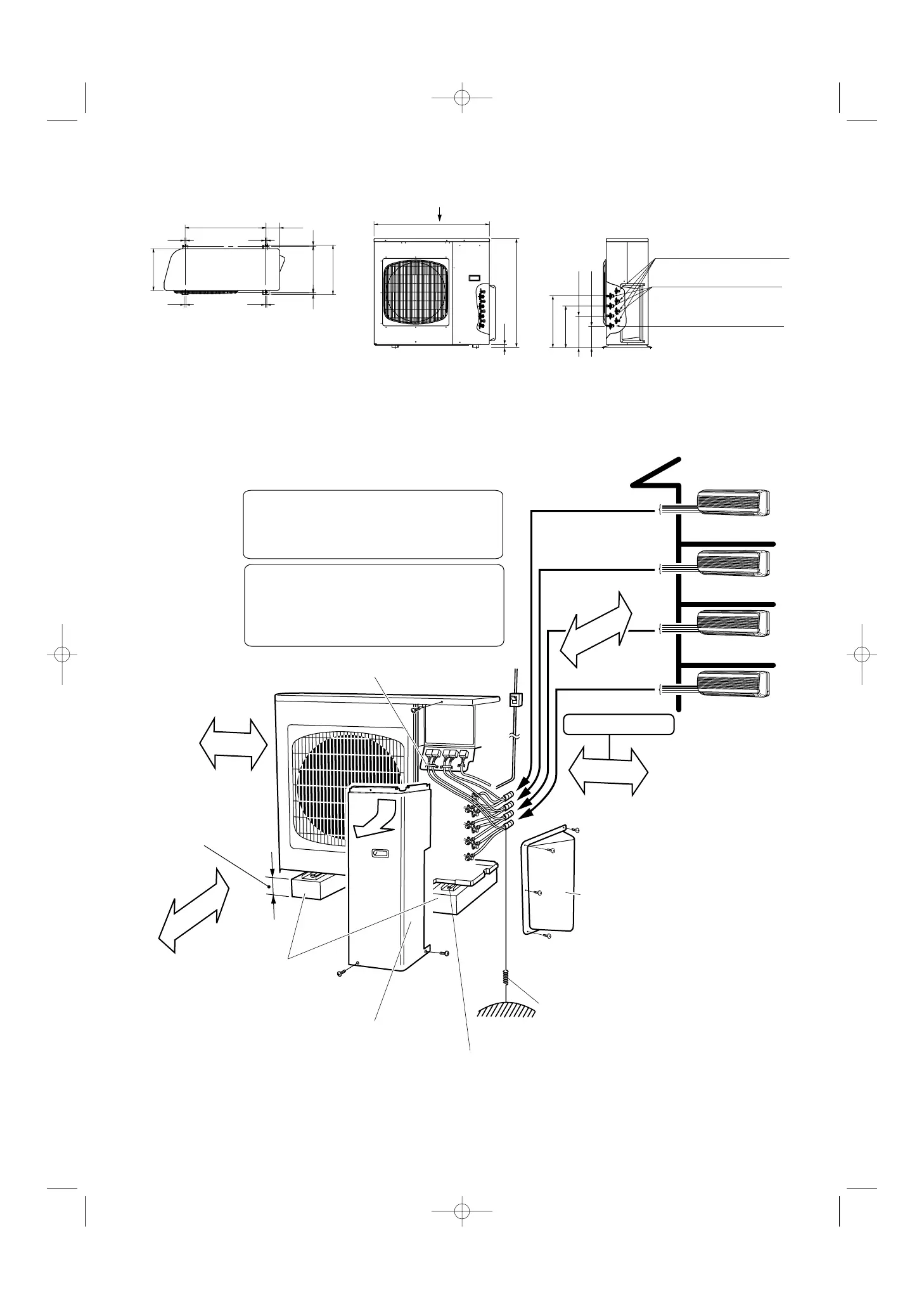
2-3. Outer Dimensions of
Outdoor Unit
2-4.
Diagram of Outdoor Unit Installation
Indoor unit A
Indoor unit B
Indoor unit C
Indoor unit D
Be sure to connect indoor and outdoor units only in
combinations that are listed in the catalog or in the
combination table that was provided with the outdoor unit.
(Use caution. Connecting any other model may result in
operation failure and malfunction.)
The dimensions indicated by ⇔ in the figure below are
spaces that are required in order to maintain
performance. Install in a location where the dimensions
indicated by ⇔ are ensured, and where 2 or more faces
of the unit are unobstructed. In principle, the top direction
should be unobstructed.
A
B
C
D
Tubing
panel
Base (not provided)
(concrete or similar material)
Ensure 150 mm
of space if a
drain hose is to
be used.
Fasten with anchor bolts
(not provided)
(3/8" or M10, 4 locations)
Inspection panel
Over 10
Over 500
Ground
wire
(not
provided)
Cable fastener
Power breaker
O
ver 250
Service space
O
ver
200
940
13 13
13 13
1015
380
405
660
110
340
880
25
256
176
336
416
A
A
Service valve on narrow tube side
(Outer diameter φ6.35)
Service valve on wide tube side
(Outer diameter φ9.52)
Service valve on wide tube side
(Outer diameter φ12.7)
Fig. 5
Fig. 6
Never install only a single indoor unit.
Unit: mm
 Loading...