11
Field Wiring - Continued
Limit Control Operation
1.
MAIN POWER SUPPLY: Depending on model
designation, the electric Hydronic Block may be
energized by alternating current service entrances: 240
volt single phase 50 or 60 cycle 3 wire plus ground.
Wire size see Table 1. Sizes listed for various capacity
units include total amperes necessary to operate
elements, circulator and zone valves where used. Wire
sizes specied conform to Canadian Electrical Code
(Canada) or National Electric Code (USA) and include
derating for ampacity and temperature. Use copper
wire only. Check state and local requirements.
A. Read data name plate before connecting unit.
Electrical connections are provided and located for
proper installation.
B. Use only copper wire of proper size and make sure
all terminations are tight. Do not use aluminum
wire.
2.
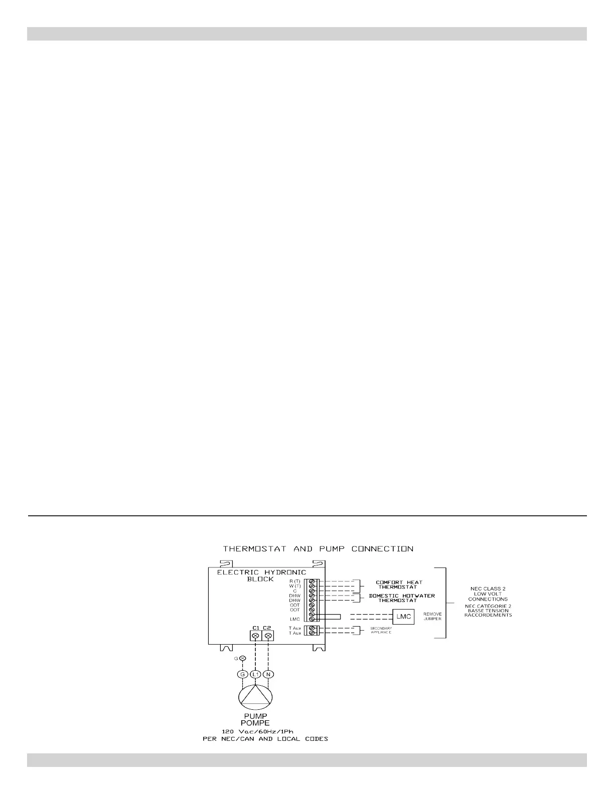
CIRCULATOR POWER SUPPLY: Terminals identied
as C1(L) and C2(N) at bottom of control panel (Figure
6) shall be used to supply one circulator pump
power. Circulator motor shall not be larger than 1/6
horsepower with maximum 5.0 amp rating. Wiring from
control panel to the pump should have insulation rated
75°C. Circuit protection is provided by 15 amp breaker
on boiler.
NOTE: If circulator pump is larger than maximum size
listed above, separate circulator pump relay must be
provided with separate overload protection. Where more
than one circulator is used for zoning, it must be installed
and protected according to approved electrical codes.
ELECTRICAL CONNECTIONS
Wiring On Control
• PUMP: Connect only 120 Vac 1/6 hp (maximum) pump
to terminals C1(L) and C2(N) on controller. Ground
screw is located on control panel. Strip wire ends before
inserting into terminal block. Tighten terminal screws.
Do not use pump rated greater than 5 amps!!
• THERMOSTAT: Two or three wire thermostat capable.
Terminals R(T), W(T) and C are provided. Two wire
thermostat use R(T) and W(T). Three wire thermostat
also use terminal C. See Figure 6. Do not apply
external power source to terminals!! Strip wire ends
before inserting into terminal block. Tighten terminal
screw clamps.
Thermostat Installation
1.
Install thermostat on inside wall ve feet above oor.
2.
NEVER install thermostat on outside wall.
3.
Do not install thermostat where it will be affected by
sunlight, drafts, televisions, lighting xtures, hot or
cold pipes, replaces, or chimneys.
4.
Instructions for nal adjustment of thermostat
(adjusting heating anticipator, calibration, etc.) are
packaged with thermostat.
5.
Recommended setting for heating anticipator is
0.1 amps.
Note: Argo AT Boiler will work with standard and
programmable setback thermostats.
Figure 6 - Thermostat and Pump Connection