10
ELECTRICAL CONNECTIONS
Boiler Wiring
NOTICE
Boiler is not designed for use of aluminum wiring.
Boiler failure can occur if aluminum wiring is used.
1.
Argo Electric Hydronic Boilers are pre-wired for use
with 240-volt, 3 wire, single-phase, 50/60-hertz power.
For reduction in boiler capacity when line voltage is less
than 240 volts see Table 1 page 6.
2.
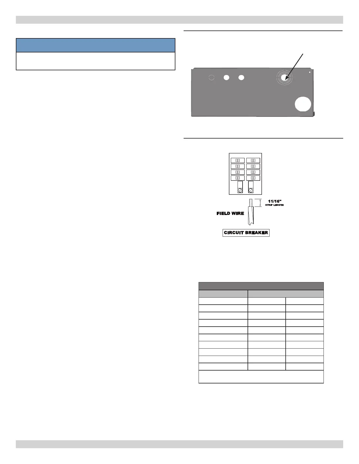
Opening provided in jacket bottom panel for eld wiring,
refer to rating chart for recommended wire sizes. See
Figure 4 for stepped Electrical Knock-out.
3.
Electrical wiring shall be in accordance with
requirements of authority having jurisdiction. Refer to:
• Canada - Canadian Electrical Code, CSA C22.1 Part 1,
Safety Standards for Electrical Installations.
• USA - National Electrical code, ANSI/NFPA 70.
4.
Verify nameplate rating and check related codes to
properly size conductors, switches and over current
protection.
5.
Stepped knockout is provided on bottom of cabinet for
different voltage connections. Wire connections refer
Figures 8 and 9 or wiring diagram on inside of boiler
front cover.
6.
All circuit breakers or disconnects ahead of boiler must
be OFF. Turn boiler integral breakers off at this time as
well. Remove boiler front cover by removing 4 screws
from top and sides.
7.
Boilers used in multiple zone system, zone valves
must be powered from independent source and have
electrically isolated end switches or isolating relays
wired in parallel to boiler thermostat terminals. Do not
attempt to power zone valves from transformer in
boiler control system.
Wire Classes - Table 2
Number of Concentric Strands
Wire Size AWG Class B Class C
10 7 19
8 7 19
6 7 19
4 7 19
3 7 19
2 7 19
1 19 37
1/0 19 37
2/0 19 37
Class B - Power cables
Class C - Power cables where more exibility is desired
Field Wiring
• All Field wiring shall be in accordance with NEC or CEC
standards.
• Minimum Circuit Ampacity (MCA) and recommended
Maximum Over-current Protection (MOP) are listed on
nameplate of unit, see Table 1.
• Use Copper conductors only.
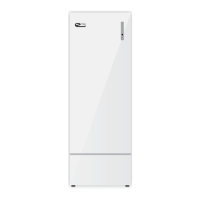
• Use only Class B or C Stranded wire. See Table 2.
• Wire Strip Length: 11/16” (Minimum). See eld wiring
diagram. See Figures 9 and 10.
• Wire must be fully inserted into terminal block.
• Field terminal wire lugs shall be securely tightened.
• Do not use wire grease on wire termination
connections. This will change torque properties.
Figure 4 - Stepped Electrical Knock-outs -
Jacket Bottom
Figure 5 - Field Wiring Diagram
Field Wiring
Entrance