8
Circulating System
• Design system as primary/secondary piping. Operate
system with maximum output temperature of 180ºF
(82°C) or lower and temperature rise across the unit of
20ºF (11°C) or lower. Refer to tables below and Figures
2 & 3.
• Return water temperature must be higher than room
temperature in which boiler is installed to prevent
condensation.
“AT” Series - 2 Element Boiler
KW Capacity Minimum Flow Rate (GPM)*
6 2.0
8 2.7
10 3.4
12 4.1
“AT” Series - 4 Element Boiler
KW Capacity Minimum Flow Rate (GPM)*
12 4.1
16 5.5
20 6.8
24 8.2
* Flow rate based on 20°ΔT
Connecting Supply And Return Piping
1.
Hot water boilers installed above radiation level must
be provided with low water cutoff device either as part
of boiler or at time of boiler installation.
2.
When boiler is connected to heating system utilizing
multiple zone circulators, each circulator must be
supplied with ow control valve to prevent gravity
circulation.
3.
Reduced pressure back ow preventer must be present
under provisions required by Environmental Protection
Agency, (EPA).
4.
Manufacturer requires plumbing arrangements as
illustrated in Figures 2 & 3. Inlet or return pipe is
located at bottom of unit. Reverse ow will result in
noisy operation and cause very early element failure.
Drain cock is to be located at lowest point of piping.
HYDRONIC PIPING
5.
Outlet or supply pipe line to radiation is located at top
of unit. Combination temperature pressure (altitude)
gauge is provided with each unit and should be
installed close to boiler outlet. It is important the gauge
sensor be completely immersed in owing water to
assure correct temperature readings.
6.
Install gate valves at locations shown in Figures 2 &
3, so any boiler servicing requiring removal of water
can be done quickly and easily. Not illustrated but
recommended is installation of air vents at high points
of hydronic system to reduce initial start up time and
help avoid element burnout during entire life of heating
system.
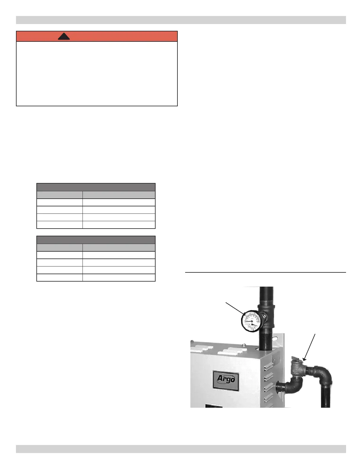
7.
Safety relief valve is supplied with each Electric
Hydronic Block and must be installed vertically. Install
at location and discharge direction shown using pipe
nipple and elbow supplied. See Figure 1. Add piping so
any water discharged will not damage boiler or other
system components.
8.
For further piping information refer to Hydronics
Institute (AHRI) manual (Installation Guide
for Residential Hydronics).
9.
Pipe the discharge outlet of the safety relief valve
within 6" of the oor.
Figure 1 - Safety Relief Valve
Safety Relief
Valve
Pressure
Gauge
WARNING
Fire, explosion, asphyxiation, burn, scald and
electrical shock hazard. System design must
incorporate primary/secondary piping to allow boiler
pump to prepurge and post purge the unit before
and after energizing the heating element. Shortened
element life and/or opening of safety relief valve
could occur. Failure to follow these instructions could
result in death or serious injury.
!