e2v technologies (uk) limited 2013 CR 114528 05 Apr 2013 DAS775571AA Version 1, page 7
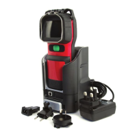
3.4 System Configuration (Charger Front)
1. Docking bay 1 (camera with battery) 5. Camera lock mechanism
2. Docking bay 2 (spare battery) 6. USB port (front)
3. Camera release button 7. Charging status LEDs
4. Camera eject mechanism 8. Front cover (removable)
Up to six chargers can be powered in a “daisychain” configuration.
Connections should be made via the green power connectors located
underneath the removable front cover. The “daisychain” power circuit contains
a replaceable 10 A fuse. This is also located underneath the removable front
cover. See section 4.3 for installation details.
3.5 System Configuration (Charger Rear)
1. USB port (rear)
2. Power connector