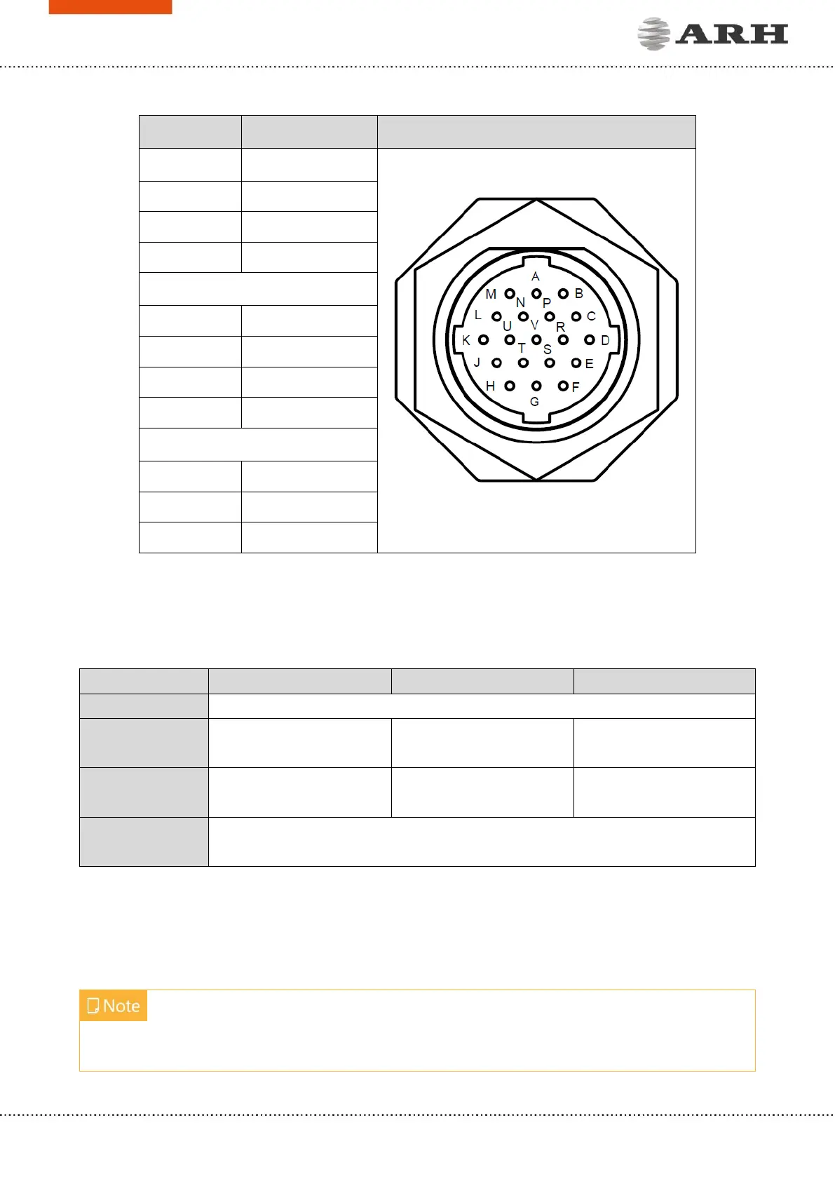
The layout of the upper user I/O connector is the following:
FRONT VIEW (CAMERA CONNECTOR SIDE)
POWER SPECIFICATIONS:
The required input voltage is model dependent, please use the proper input according to your
model. Furthermore, please be aware that voltage drop can occur when using cables.
7W – 14W
(max. 31W with heating)
8W – 15W
(max. 32W with heating)
11W – 17W
(max. 20W with heating)
Input Current
*without heating
0.3A (max. 2.5A transients
occur for a few msecs)
0.4A (max. 2.5A transients
occur for a few msecs)
0.5A (max. 2.5A transients
occur for a few msecs)
TRIGGER SPECIFICATIONS:
Input: min. 5V, max. 12V Logic Output: min. 5V, max. 12V, max. 10mA
Pulse width: min. 1 ms
Mind the polarity.