EN - 34
2. If there is less than 1/16" (1.6 mm) gap
be
tween brake pad and belts, loosen
idler adjustment nut and move id
ler
aw
ay from belt. Position idler to
achieve
a
1/16" (1.6 mm) minimum brake p
ad
ga
p and a 1/2 – 7/8" (12.7 – 22.2 m
m)
ga
p between the plastic roller and t
he
f
rame.
IMPORTANT: If adjustments cannot be
brought into specified ranges see your Dealer
for repairs.
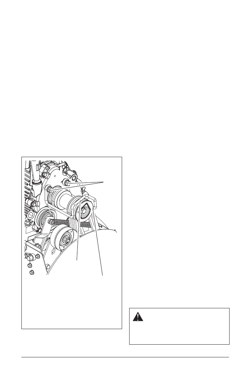
Check Belt Finger Clearance
1. With attachment clutch lever engaged,
the belt finger located opposite the belt
idler must be less than 1/8" (3 mm) from
belts, but not touching the belts
(Figure 37).
To adjust belt finger, loosen the bolts and
move the finger to the proper position.
Tighten the bolts and recheck the belt
finger clearance.
2. Replace the belt cover and tighten
hardware.
TRACTION DRIVE CLUTCH
ADJUSTMENT
If drive slips, adjust traction clutch to
compensate for friction disc wear.
1. Loosen jam nut on traction
cable
adjust
ment barrel. Turn adjustment
barrel down to shorten cable
and
rem
ove all cable slack.
2. With traction clutch disengaged, chec
k
t
hat drive plate finger touches the side of
hole closest to auger hous
ing
(F
igure 40).
ATTACHMENT DRIVE BELT
REPLACEMENT
Remove old attachment drive belts:
1. Shut off engine, remove key, disconnect
spark plug wire and allow unit to
cool
c
ompletely.
2. Loosen hardware securing belt cover to
unit.
NOTICE: DO NOT completely remove the
hardware from unit.
3. Remove belt cover.
4. Models 921028, 029: Remove chut
e
gear cov
er.
5. Rotate discharge chute all the way to the
left (as viewed from the operator’
s
posit
ion).
6. Models 921023, 024, 030, 032, 035,
036, 037: Remove spring clip from chute
crank and separate.
Models 921028, 029: Remove
hairpin
f
rom discharge chute rod and separate.
7. Disconnect chute lock cable and chut
e
def
lector cap cable (if equipped).
8. Remove belt finger (Figure 37).
9. Remove attachment drive belt from
engine sheave (it may be necessary to
turn engine sheave using recoil starter
handle).
IMPORTANT: To avoid bending bottom cover
when tipping unit apart, support handlebars
firmly or tip unit up on housing and remove
bottom cover by removing six cap screws
before separating unit.
10. Support Sno-Thro frame and housing.
Figure 37
Check belt finger clearance here. With the
attachment clutch engaged, there should
be less than 1/8" (3 mm) clearance
between the belts and the belt finger. The
belt finger should not touch the belts.
1. Mounting Hardware
2. Belt Finger
1
2
CAUTION: Always support Sno-
Thro frame and blower housing
when loosening the cap screws
holding them together. Never
loosen cap screws while unit is in
service position.