EN - 35
11. Remove hex bolts securing housing to
frame (two on each side). Tip hous
ing
an
d frame apart on pivot pin (Figure 38).
12. Remove attachment drive belts from
attachment pulley (hold brake away from
belt).
Install New Attachment Drive Belts
1. Place new attachment belts onto
attachment pulley.
NOTICE: Holding down the attachment clutch
lever will make it easier to reconnect the
housing and frame.
2. Tip housing and frame back toget
her
an
d secure with hex bolts.
3. Place belts onto engine sheave.
4. Reposition and secure belt finger.
IMPORTANT: With attachment clutch lever
engaged, belt finger on the side opposite the
belt idler should be less than 1/8" (3 mm)
from belt, but not touching the belt. Adjust
belt finger as necessary.
5. Check adjustment. See Attachment
Clutch/Brake Adjustment on page 32.
6. Reconnect chute lock cable, chut
e
def
lector cap cable, chute crank
and
sec
ure.
7. Models 921028, 029: Reinstall chut
e
gear cov
er.
8. Replace belt cover and tight
en
hardwar
e.
TRACTION DRIVE BELT
REPLACEMENT
NOTICE: Replacement will be easier with
housing and frame tipped apart and bottom
cover off.
1. Remove attachment drive belts (s
ee
Rem
ove old attachment drive belts: on
page 34).
2. Detach traction idler spring.
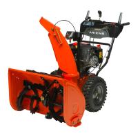
Figure 38
Models 921023, 024, 030, 032, 035, 036,
037
Models 921028, 029
1. Belt Cover
2. Chute Gear Cover
3. Discharge Chute Rod
4. Chute Lock Cable
1
2
3
4
1
3
2
WARNING: AUGER / IMPELLER
MUST STOP within 5 seconds
when attachment clutch lever is
released or unit damage or serious
injury may result.
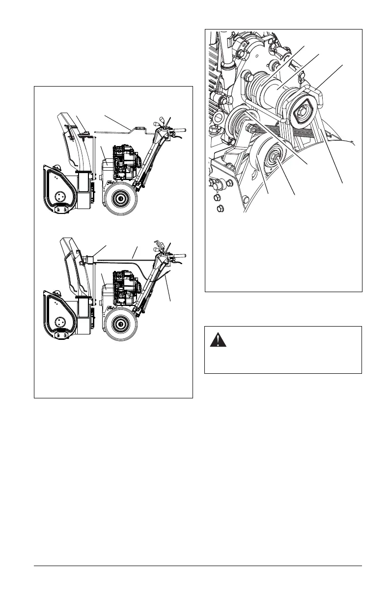
Figure 39
1. Traction Drive Belt
2. Engine Sheave
3. Attachment Drive Belts
4. Belt Finger
5. Attachment Belt Idler
6. Attachment Idler Adjustment Nut
7. Traction Belt Idler
2
1
3
4
5
6
7