EN - 36
3. Remove swing gate spacer and slide
dr
ive plate over so that finger clears stop
hole in frame and can swing past it
(Figure 40).
NOTICE: The drive plate is detached to
create space between the drive plate and
friction disc to remove and reinstall the belt.
4. Pull idler away from traction drive belt
and remove belt from idler pulley, engine
sheave and driven pulley (it may be
necessary to turn engine pulley usi
ng
r
ecoil starter handle).
5. Install new traction drive belt ont
o driven
pulley and
engine sheave.
6. Swing drive plate toward friction disc
until finger lines up with stop hole
in
f
rame. Slide drive plate over, insert
ing
f
inger into stop hole. Reinst
all swing
gat
e spacer.
7. Reinstall traction idler spring.
NOTICE: Make sure the drive plate assembly
return spring remains connected to the drive
plate and the frame. Make sure the swing
gate pivot bushing is piloted in the pivot hole
in the frame.
8. Replace attachment drive belt (S
ee
Ins
tall New Attachment Drive Belts
on
p
age 35).
FRICTION DISC REPLACEMENT
1. Shut off engine, remove key, disconnect
spark plug wire and allow unit to
cool
c
ompletely.
2. Place unit into service position on a level
surface.
3. Remove both wheels.
4. Remove bottom cover by removing si
x
hex bolt
s.
5. Disconnect pivot pin from t
he speed
selec
tor arm. Save the hardware fo
r
reins
tallation.
6. Remove spring clip nearest
drive
spr
ocket from hex shaft.
7. Remove left bearing flange from frame.
8. Slide hex shaft to the left to remove
pinion sprocket and friction disc
assembly from hex shaft.
NOTICE: Be sure to save washers between
bearing and speed selector arm for
reassembly.
9. Remove friction disc assembly from
frame.
10. Remove three screws holding fricti
on
disc
to carrier bearing.
11. Remove old friction disc. Put t
he new
f
riction disc in place, cup side to ca
rrier
bearing.
12.
Reinstall three screws onto new fricti
on
disc and carrier bearing.
Torque to
5 – 6 lbf-ft (6.78 – 8.14 N•m).
13. Insert new friction disc assembly into
frame. Install washers onto carrier
bearing and slide into speed select
or
arm
.
14. Slide hex shaft through new friction disc
assembly. Install pinion sprocket ont
o
hex shaft and slide shaft into right
bearing.
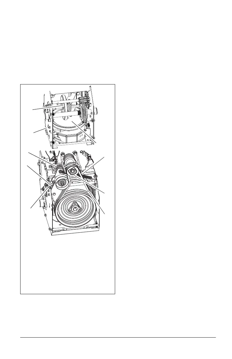
Figure 40
1. Swing Gate Spacer
2. Drive Plate Assembly
3. Traction Belt Idler
4. Attachment Drive Belts
5. Traction Drive Belt
6. Engine Sheave
7. Friction Disc
8. Drive Plate Finger
9. Swing Gate Pivot Bushing
2
3
6
1
7
4
8
5
9