EN - 37
15. Install left bearing using hardware
removed in step 7.
16. Reinstall clip pin into hex shaft.
17. Connect pivot pin to speed selector arm
(see Speed Selector Adjustment on
page 31)
18. Replace bottom cover.
19. Install wheels.
20. Return unit to upright position.
21. Connect spark plug wire to spark plug.
22. Adjust traction drive clutch (see Traction
Drive Clutch Adjustment on page 34).
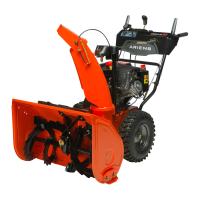
TRACK TENSION ADJUSTMENT
(Model 921023)
(Figures 42 and 43)
Check the track tension by applying pressure
on the track midway between the upper and
rear track rollers. Deflection should be
approximately 3/8" (9.6 mm) (Figure 42).
If deflection is excessive, tighten the track
tension.
If unit pulls to the left or right when a straight
path is desired adjust the track tension. If the
unit is pulling to the left, tighten the left track
adjuster. If the unit is pulling to the right,
tighten the right track adjuster.
To adjust (Figure 43):
1. Tighten the adjuster nut to tighten the
track tension.
Loosen the adjuster nut to reduce track
tension.
2. Check that unit tracks straight with no
pulling to either side.
HEIGHT ADJUSTER CABLE
ADJUSTMENT
(Model 921023)
(Figure 44)
1. Make sure that height adjustment lock
finger is fully engaged (Figure 44).
2. Loosen jam nuts on cable mount
bracket.
3. Adjust the jam nuts to remove all cable
slack and bring the overtravel arm into
slight contact with the right end of the
slot in the height adjuster lock finger.
4. Tighten the jam nuts.
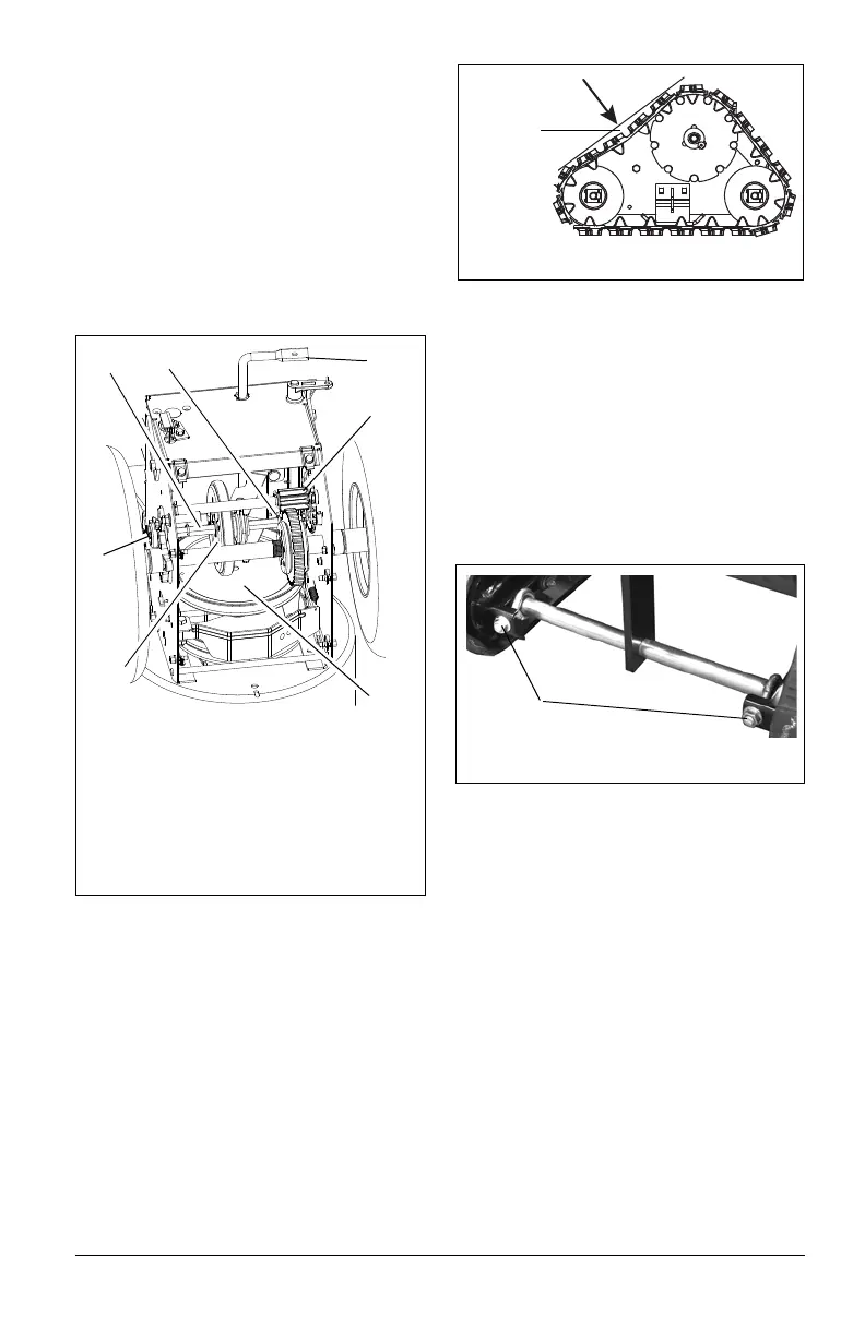
Figure 41
1. Hex Shaft
2. Bearing Flange
3. Speed Selector Arm
4. Friction Disc
5. Spring Clip
6. Drive Plate Assembly
7. Drive Sprocket
2
4
1
5
3
6
7