EasyManua.ls Logo

Ariens GRAVELY User Manual

Ariens GRAVELY
12 pages
To Next Page IconTo Next Page
Page #1 background imageLoading...
Page #1 background image
EN - 1
Log Splitter
Setup Instructions
Instructions Pour La Mise En Place
Instrucciones Para Su Montaje
IDENTIFICATION
1. Draw Bar
2. 1/2 x 1" Hex Bolt (4)
3. 1/2" Hex Nut (4)
4. P-Clamp
5. Safety Chain
6. Front Stand
7. Front Stand Lock Pin
8. Hydraulic Cylinder
9. Control Lever
10. Splitter Wedge
11. Beam
12. Rear Stabilizer
13. Stripper Plate
14. Beam Lock
15. Clevis Pin
16. Cotter Pin
17. Control Valve
18. ISO 32 Hydraulic Fluid (part # 00069100) – Not Included
19. 3/8 x 1" Hex Bolt (1)
20. 3/8" Hex Nut (1)
1
10
9
6
5
3
2
18
11
17
12
13
14
7
15
16
4
8
Not
Included
19
20
© Copyright 2013 Ariens Company
02/13
04582200A
Tools Required:
Two 3/4" wrenches or sockets
Two 9/16" wrenches or sockets
One 1/2" wrench or socket
One 3/8" wrench or socket
Thin-nosed pliers
Wire cutters
Question and Answer IconNeed help?

Do you have a question about the Ariens GRAVELY and is the answer not in the manual?

Ariens GRAVELY Specifications

General IconGeneral
BrandAriens
ModelGRAVELY
CategoryLog Splitter
LanguageEnglish

Summary

Log Splitter Setup Instructions

Log Splitter Identification

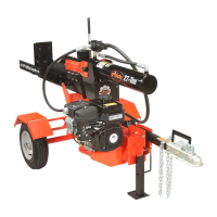
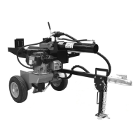
Lists and identifies all parts of the log splitter for assembly and reference.

Crate Removal and Preparation

Remove shipping materials, cut straps, and prepare the unit from its crate.

Draw Bar Attachment to Frame

Remove shipping bolts and attach the draw bar to the frame using specified hardware.

Front Stand and Draw Bar Finalization

Fold and lock the front stand, then secure the draw bar with bolts and nuts.

Beam Lock and Beam Positioning

Ensure beam lock engages and position the beam horizontally until it locks.

Stripper Plate Removal

Remove hex bolts retaining stripper plates from each side.

Wedge and Cylinder Preparation

Remove hair pin, washer, and clevis pin retaining wedge to cylinder.

Hydraulic Cylinder Installation

Position the hydraulic cylinder into the beam yokes and install one stripper plate.

Wedge and Cylinder Reassembly

Slide wedge back to cylinder and reinstall clevis pin, washer, and hair pin.

Control Lever and Stripper Plate Installation

Install control lever, reinsert clevis pin, and install remaining stripper plate.

Hydraulic Hose and Frame Attachment

Attach hydraulic hose to draw bar using P-clamp, bolt, and nut.

Initial Operation and Fluid Check

Add hydraulic fluid, check oil, start engine, cycle cylinder, and re-check fluid.

Related product manuals