Do you have a question about the Arista 7800 Series and is the answer not in the manual?
Defines the intended audience and supported Arista Networks Data Center Switches.
Instructions for checking shipping boxes, contents, and potential damage upon receipt.
Outlines the sequential steps required for installing the switch.
Directs users to external documents for safety and translated warnings.
Provides methods for contacting Arista support for technical assistance.
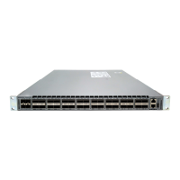
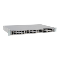
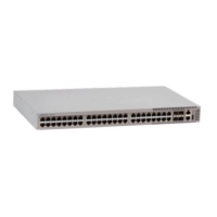
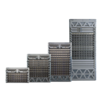
Details technical specifications for modular Arista Data Center Switches.
Criteria for choosing an installation site, including clearance and environmental factors.
Lists the necessary tools and parts for performing the switch installation.
Procedure for safely unpacking and transporting the modular switch chassis.
Guidelines to prevent damage from static electricity during installation and servicing.
Steps for installing rack nuts into unthreaded racks using a provided template.
Procedure to install and fasten the rack mounting cradle to the rack posts.
Instructions for placing the switch onto the cradle and securing it within the rack.
Guidance on connecting power supplies, including recommended bay population order.
Instructions for connecting the chassis grounding to the data center ground.
Details on connecting AC power supplies, including connectors and power cables.
Details on connecting DC power supplies, including lead pairing and length.
Steps for preparing stranded wiring and lugs for DC power connections.
Lists the power supply specifications for supported PSUs.
Details recommended power supply configurations and minimum requirements.
Explains redundant power configurations and compliance with electrical codes.
How to connect console, management, and USB ports on supervisor modules.
Instructions for installing SFP, QSFP, OSFP optic modules in line card ports.
Overview of supervisor module indicators, including system level status LEDs.
Explains the status LEDs for line card modules and their port status.
Describes the status LEDs for fabric modules and fan modules.
Details the status LEDs for AC and DC power supply modules.
Lists common cables and items included in accessory kits for rack mounting.
Details specific parts provided in accessory kits for four-post rack installations.
Tools and procedures for removing and inserting line cards and supervisor modules.
Procedures for removing and installing AC and DC power supplies.
Steps for removing and installing fabric and fan modules.
Procedure for removing and replacing a fan module within a fabric module.
Process for removing and installing supervisor modules.
Procedures for removing and installing line cards and their blanks.
Lists the Regulatory Model Numbers (RMNs) for the product models.
Provides Taiwan RoHS information and links to relevant tables.