24 /
INSTALLATION
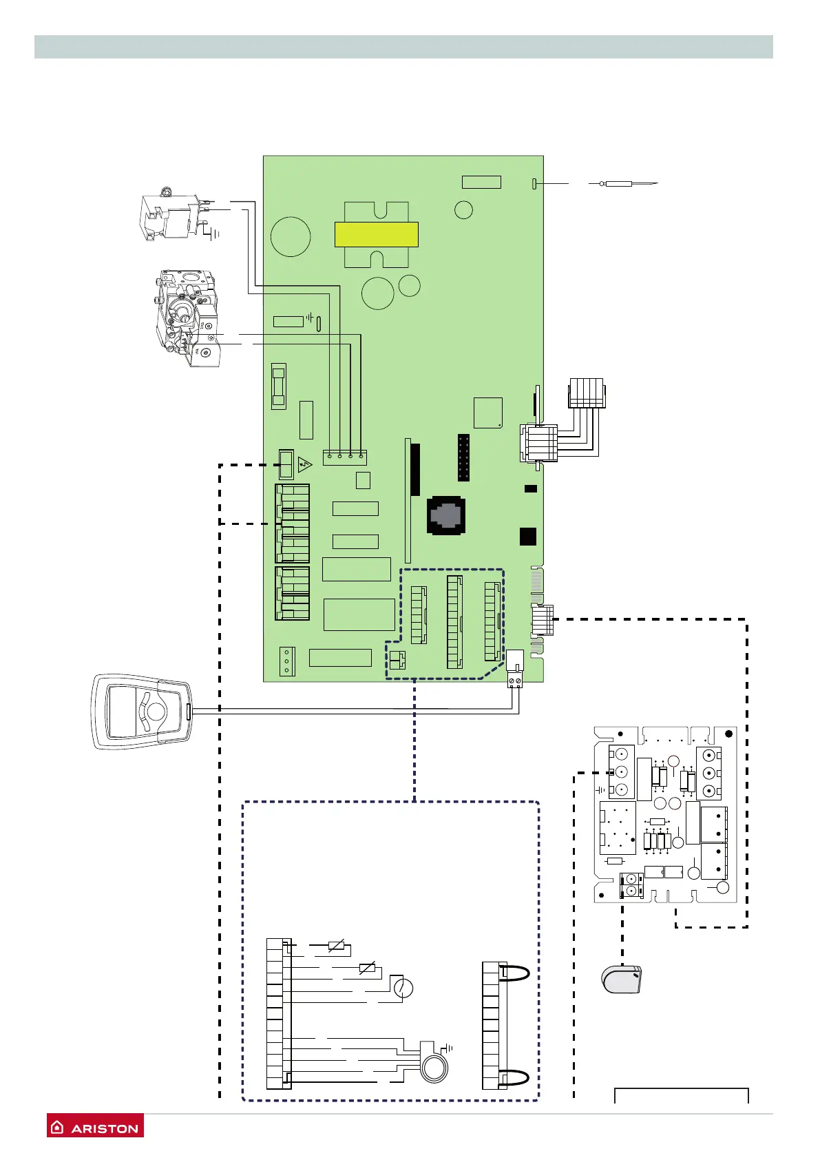
Electrical diagram
For increased safety, ask a qualified technician to perform a thorough
check of the electrical system.
The manufacturer is not responsible for any damage caused by the
lack of a suitable earthing system or by the malfunctioning of the
electricity mains supply.
CN14
DISPLAY
CN25
CN17
CN19
CN26
FAST FUSE 2A
1
CN05
FLAME
CN04
EARTH
1234
CN22
N L
CN20
FILLING EXT. P.
1 2 3 4
CN12
FAN PUMP
PUMP
SPEED
1 2 3 4 5 6
CN10
DIV. VALVE
CN08
8 7 6 5 4 3 2 1
CN11
1213 11 10 9 8 7 6 5 4 3 2 1
CN12
11 10 9 8 7 6 5 4 3 2 1
CN24
CN21
5 4 3 2 1
2
1
CN16
Detection
electrode
5
1
Display
Ignitor
Gas valve
Modulating fan
Thermal fuse
C.H. flow temp.probe
1213 11 10 9 8 7 6 5 4 3 2 1
CN24
11 10 9 8 7 6 5 4 3 2 1
C.H. return temp.probe
Remote
control
(optional)
DZ2
CN2
IC1
CN5
1
CN7
D2
1
1
CN1
1
CN8
R8
R1
C3
11
CN6
C1
R7
R5
DZ1
++
C2
R3
R2
D3
++
C4
D1
R6
D4
CN4
1
CN3
R4
IC2
MH4
MH2MHOLE
DHW
OUTDOOR
1
OFF
N
L
DHW
ON
CH
PUMP L
L
RT
B
M
B
M
G
G
M
M
N
N
Bl
R
B
N
M
G
N = Black
B = Blue
Bl = White
R = Red
V = Green
M = Brown
G = Grey
NOTE: For separate
2 zone temperature
management with an
outdoor sensor con-
nected contact the
Technical Help Desk
on 0870 241 8180
 Loading...