For coaxial systems, the maximum development value, mentio-
ned in the table below also takes into account an elbow.
For twin ue systems the maximum development value, mentio-
ned in the table includes the exhaust gas/air intake terminal.
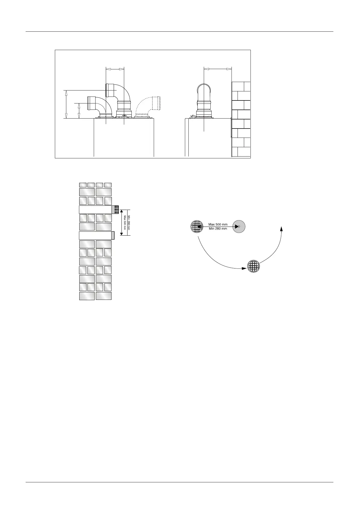
Type 5 outlets should respect the following instructions:
1- Use the same ø 80 mm ue pipes for the air intakes and
exhaust gas ducts.
2- If you need to insert elbows in the air intake and exhaust gas
ducts, you should consider for each one the equivalent length
to be included in the calculation of developed length.
3- The exhaust gas duct should jut above the roof by at least 0.5 m.
4- The intake and exhaust gas ducts in Type C13 + C53 must be
installed on the same wall, or where the exhaust is vertical and
the air intake horizontal, the terminals must be on the same
side of the building.
EXHAUST
AIR INTAKE
AIR INTAKE
AIR INTAKE MUST NOT BE
FITTED ABOVE THE EXHAUST
Fig. 9
Fig. 10
 Loading...