23
installation
WARNING
Before performing any work on the boiler, rst
disconnect it from the electrical power supply using
the external bipolar switch and remove the fuse.
Electrical connections
For increased safety, ask a qualied technician to perform a
thorough check of the electrical system.
The manufacturer is not responsible for any damage caused by
the lack of a suitable earthing system or by the malfunctioning of
the electricity mains supply.
Make sure that the system is able to withstand the maximum
power absorbed by the boiler (this is indicated on the appliance
data plate). Check that the section of the wires is suitable and is
not less 1.5 mm
2
The appliance must be connected to an eecient earthing system
if it is to operate correctly.
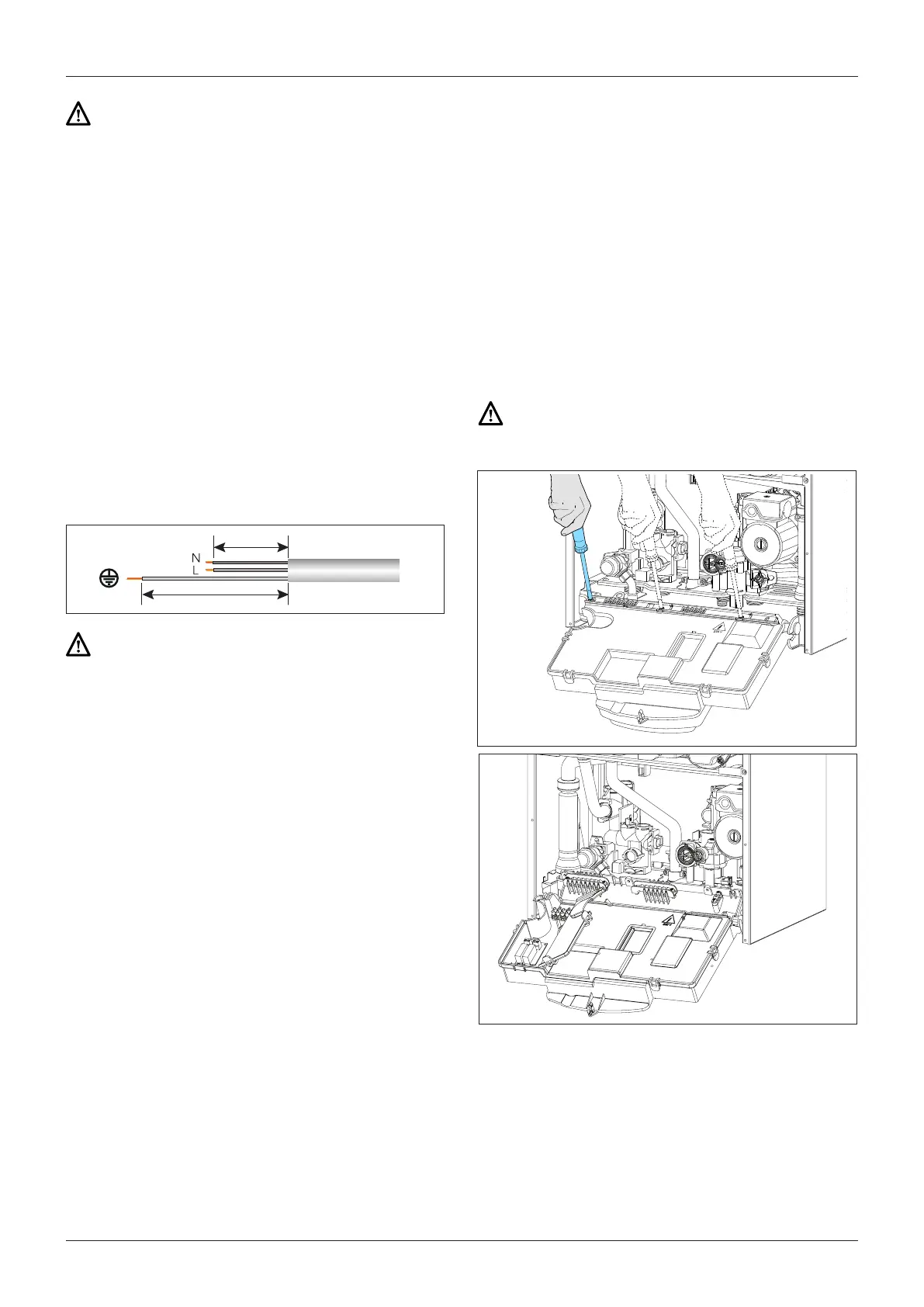
The power supply cable must be connected to a 230V-50Hz
network, where the L-N poles and the earth connection are all
respected.
Important!
In the event that the power supply cable must be changed, replace
it with one with the same specications.
Power supply cable
Important!
Connection to the electricity mains supply must
be performed using a xed connection (not with a
mobile plug) and a bipolar switch with a minimum
contact opening of 3 mm must be tted.
The use of multiplugs, extension leads or adaptors is strictly
prohibited.
It is strictly forbidden to use the piping from the hydraulic, heating
and gas systems for the appliance earthing connection.
The boiler is not protected against the eects caused by lightning. If the
mains fuses need to be replaced, use 2A rapid fuses.
Peripheral unit connection
To access peripheral unit connections carry out the following
steps:
- Disconnect the boiler from the power supply
- Remove the casing by unhooking it from the instrument
panel
- Rotate the control panel while pulling it forwards
- Unscrew the three screws on the back cover of the instrument
panel
- Unhook the right side clip and the right front clip; then lift the
ap
The terminal block (see gure) may be accessed in order to connect:
Outdoor sensor
Room thermostat 1
Optional P.C.B.s can also be installed for further accessories:
BUS P.C.B. Clima Manager
Modulating Room Sensor
Programmable Room Thermostat
Outdoor Sensor
Caution!
For the connection and positioning of the wires
belonging to optional peripheral units, please refer to
the installation manuals of these units.

 Loading...