25
installation
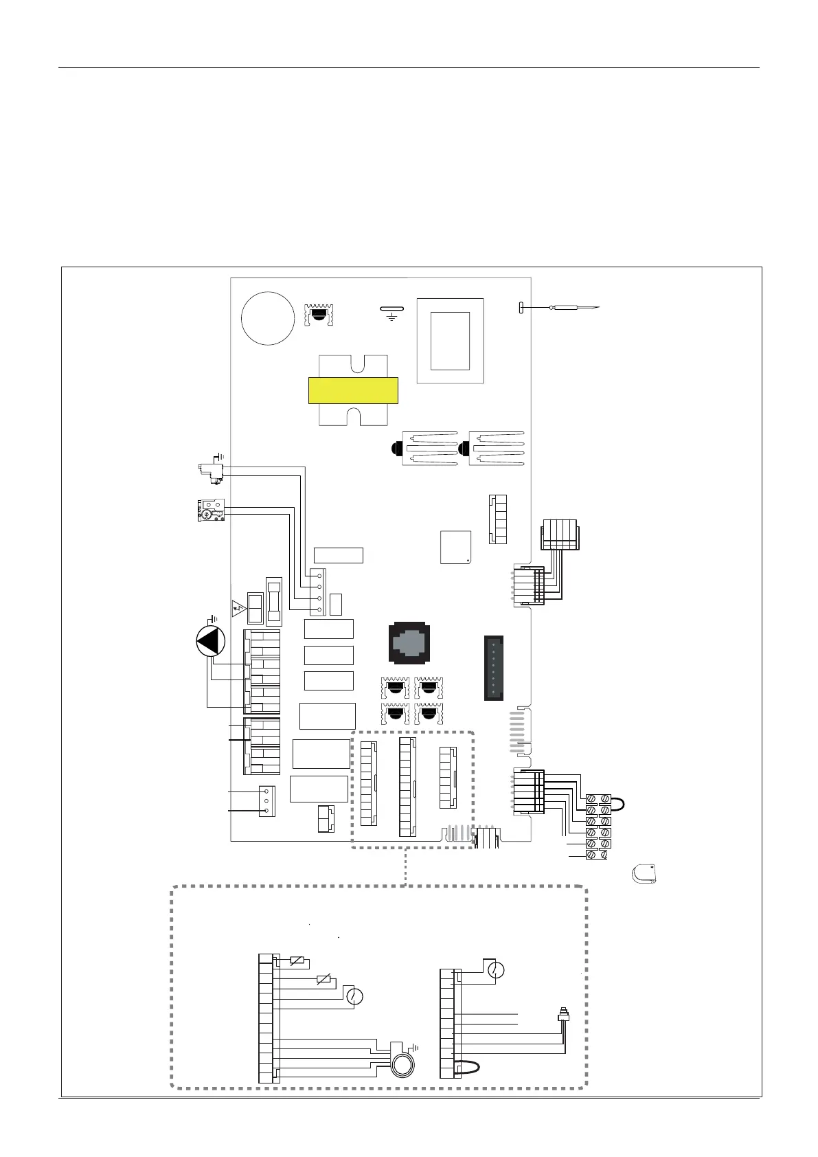
Electrical diagram
For increased safety, ask a qualied technician to perform a
thorough check of the electrical system.
The manufacturer is not responsible for any damage caused by
the lack of a suitable earthing system or by the malfunctioning of
the electricity mains supply.
ROOM
FLOOR
OTS
CN1
CN16
CN21
DISPLAY
CN2
CN25
FLOW
CN14
TIMER
CN15
FAN
PUMP + SPEED
DIVERTR VALVE
ZONE + FILLING
FET5
FET1
FET4
FET3
FET2
CN11
FAST FUSE 2A
1
8
REMOTE CONTROL
CN24
CN6
FLAME
CN5
EARTH
CN19
1234
CN3
N L
CN20
FILLING EXT. P.
1 2 3 4
CN12
FAN PUMP
PUMP
SPEED
1 2 3 4 5 6
CN10
DIVERTER
VALVE
CN9
6 5 4 3 2 1
EPROM KEY
CN18
8 7 6 5 4 3 2 1
CN7
1213 11 10 9 8 7 6 5 4 3 2 1
CN22
11 10 9 8 7 6 5 4 3 2 1
CN4
2
1
CN17
Electrode
ionisation
5
1
Affichage
Thermostat
dʼambiance
Thermostat
plancher
chauffant
Sonde
extérieure
6
1
Allumeur
Vanne
Gaz
Circulateur
Electrovanne
remplissage
Vanne
distributrice
Débistat
sanitaire
Sonde sanitaire
P
Sonde pression
circuit primaire
Sécurité
surchauffe
11 10 9 8 7 6 5 4 3 2 1
CN4
Ventilateur
Thermofusible
échangeur
1213 11 10 9 8 7 6 5 4 3 2 1
CN22
Sonde retour
circuit primaire
Sonde départ
circuit primaire
ignitor
detection
electrode
gas
valve
display
room
thermostat
underoor
heating
external
sensor
circulation
pump
C.H. ow
temp. probe
thermal fuse
modulating
fan
overheat
thermostat
C.H. return
temp. probe
switch On-O

 Loading...